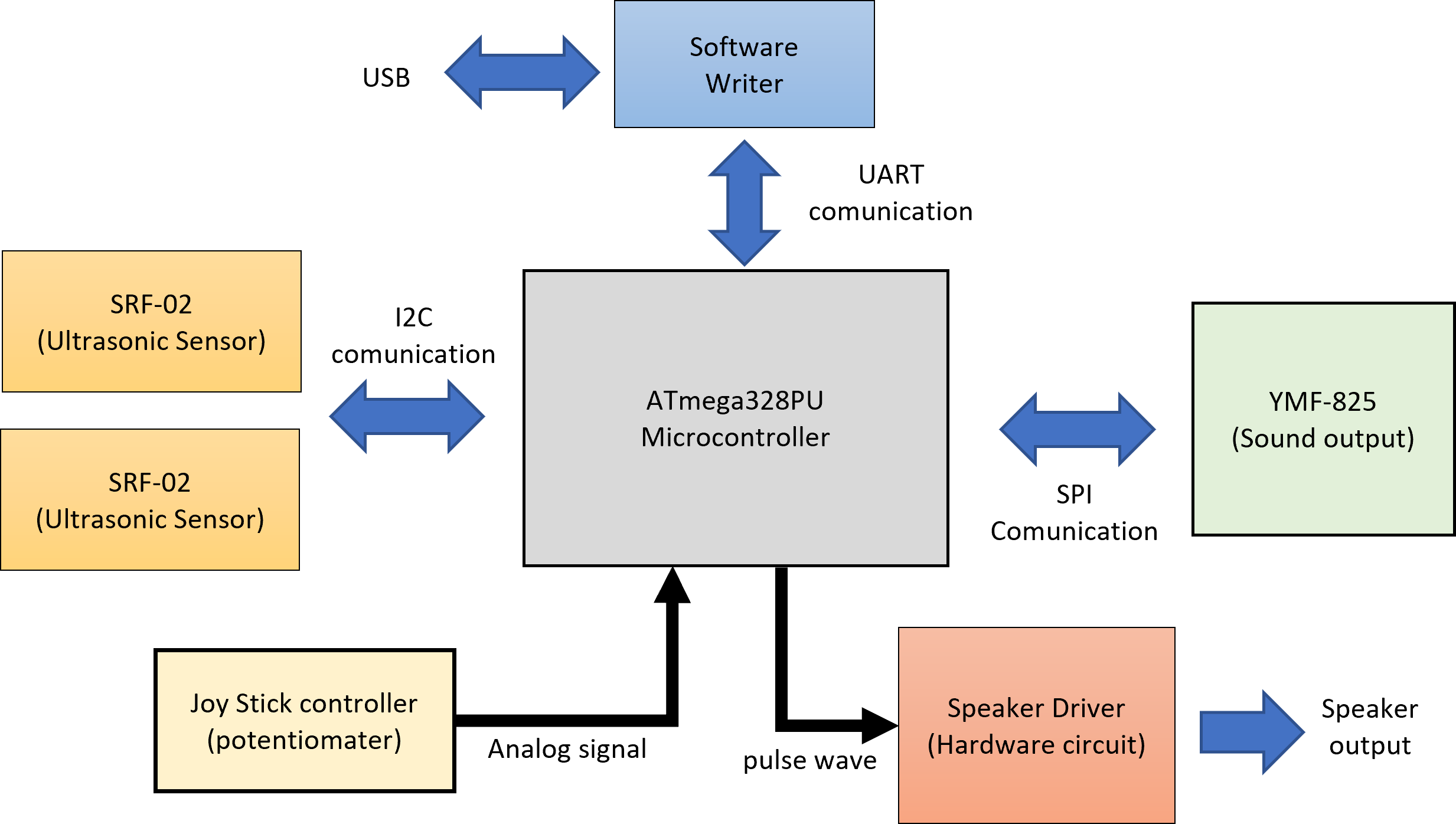
In the previous blog, I even designed a block diagram of an ultrasonic musical instrument. I will start circuit design at once. The following is the block diagram designed last time.
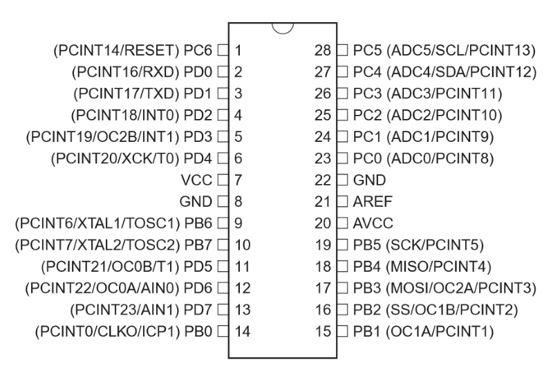
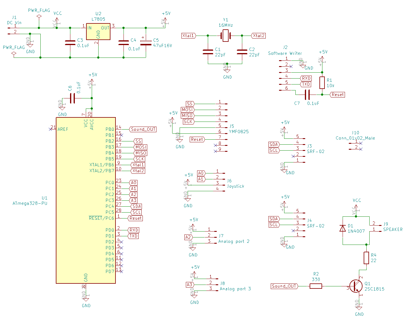
In short, how to connect each module to the microcomputer is important. First, check the pin layout of the microcomputer to be used.
pin asign ATmega328PU
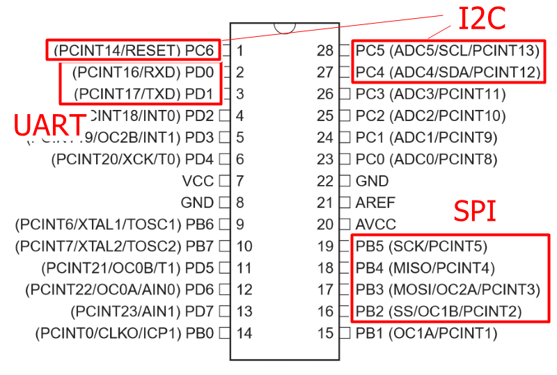
Communication port of ATmega328PU
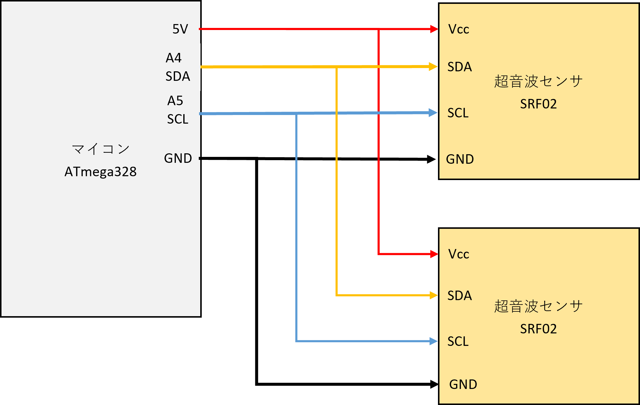
Connected to SRF-02
SRF-02 communicates in the format of I2C.
I2C connection method is very easy. This time, we will make it possible to connect two ultrasonic sensors in parallel.
For I2C communication, connect the four terminals of Vcc and GND power supply terminals, synchronous clock SCL, and signal line SDA of the sensor (Slave) and microcomputer (Master), respectively.
Even if they are connected in parallel, there is no problem because the addresses are assigned to each sensor.
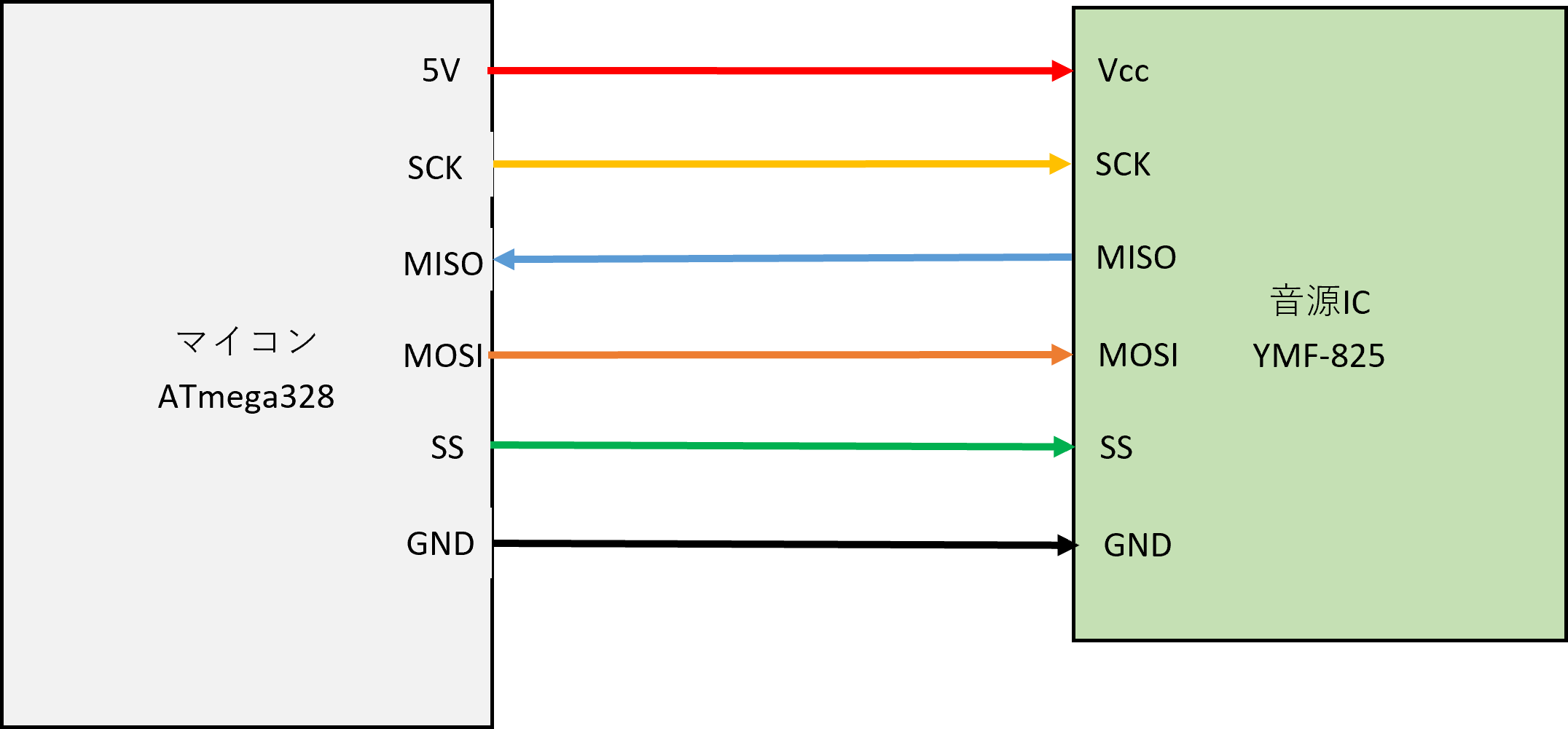
Connected to YMF-825
YMF-825 communicates by SPI.
SPI communication is from Vcc and GND power terminals on the sound source IC (Slave) and microcomputer (Master), SS (Slave Select) that selects the SCK of the synchronization clock and the Slave to be connected, and from Master to Slave. There are MOSI (Master Out Slave In) that sends a signal and MISO (Master In Slave Out) that sends a signal from Slave to Master, and it consists of a total of 6 lines.
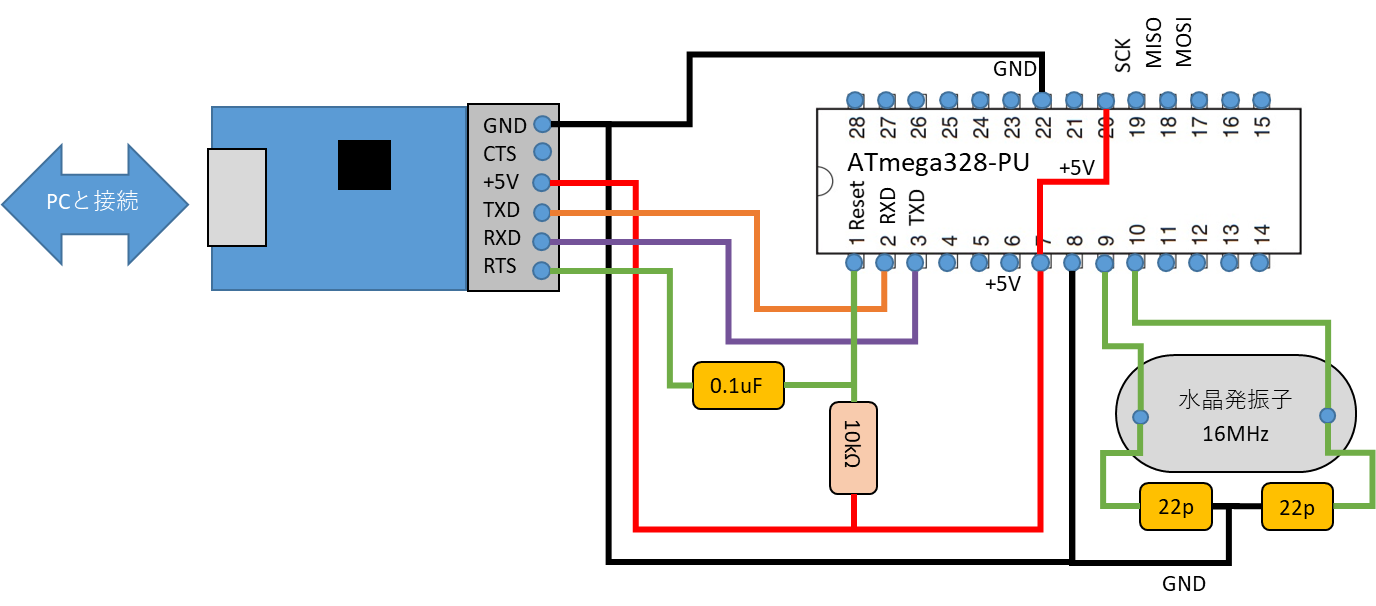
Since soft writing communicates via UART, connect the TXD (transmission) of the converter to the RXD (receive) of the ATmega328, and connect the RXD (receive) of the converter to the TXD (transmission) of the ATmega328. After that, the + 5V and GND of the TTL converter are also supplied to the ATmega328. Then, connect the RTS and the ATmega328 Reset via a 0.1uF capacitor so that the converter can send a reset signal.
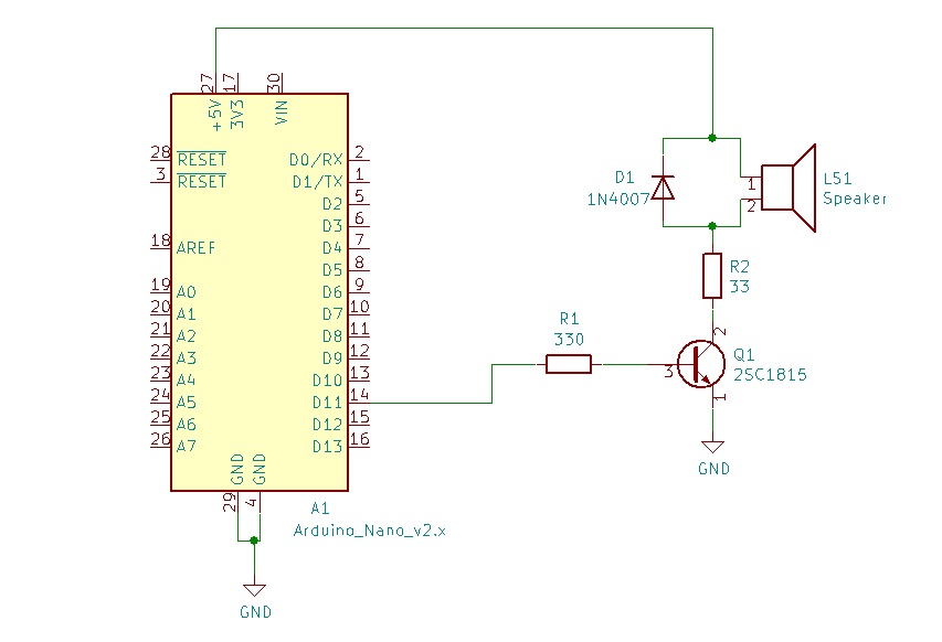
Speaker Driver
Depending on how you use YMF-825, you may run out of memory. For such a case, we have prepared a speaker driver circuit that can produce simple electronic sounds.
In the previous blog, I disassembled this case and searched for its true identity. As a result, it was a watch, but I made it before, and I gave up because it would be too expensive to have six Gixie tubes.
Therefore, since there is this fashionable case, I wondered if it could be applied to something at least.
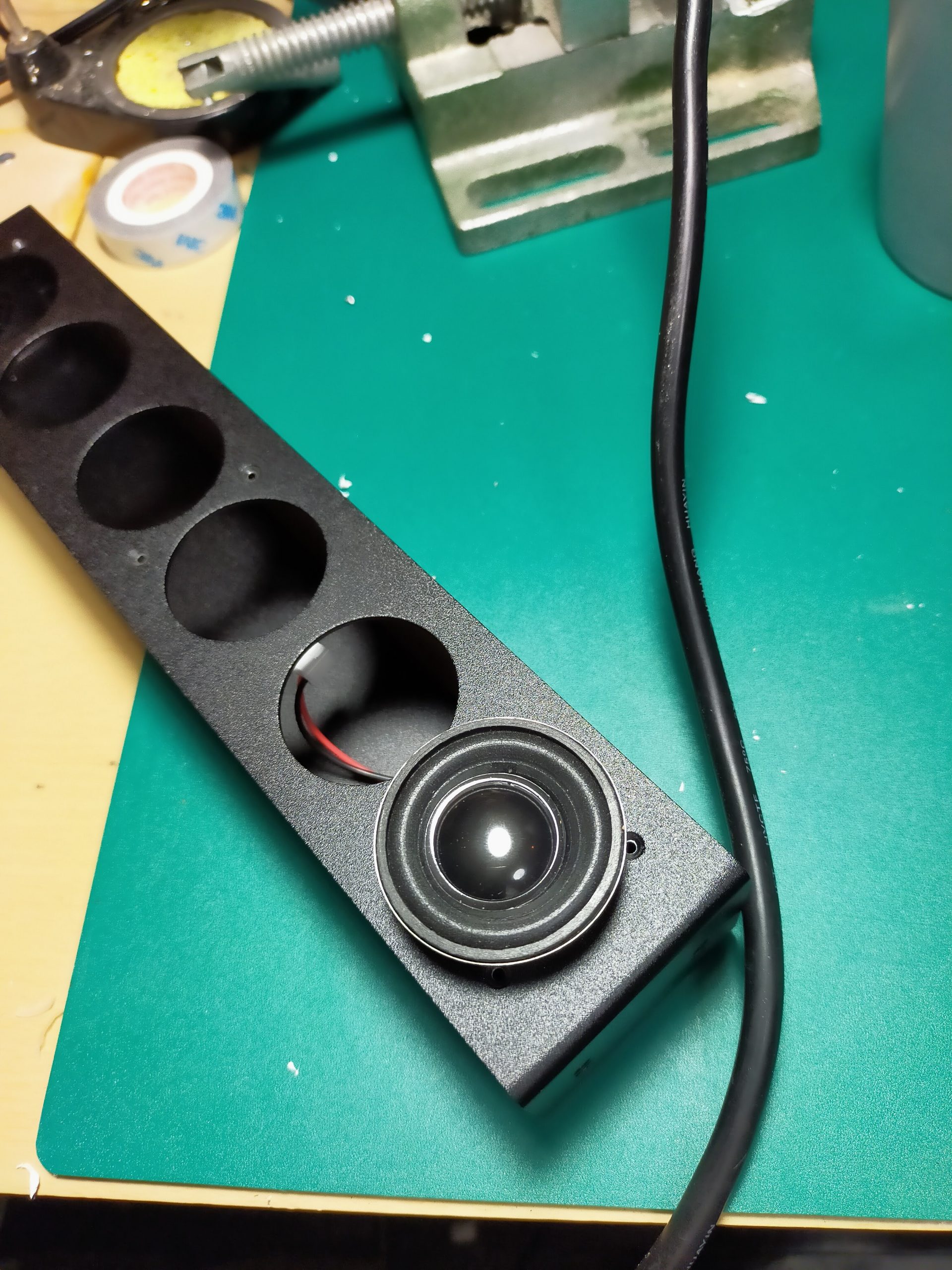
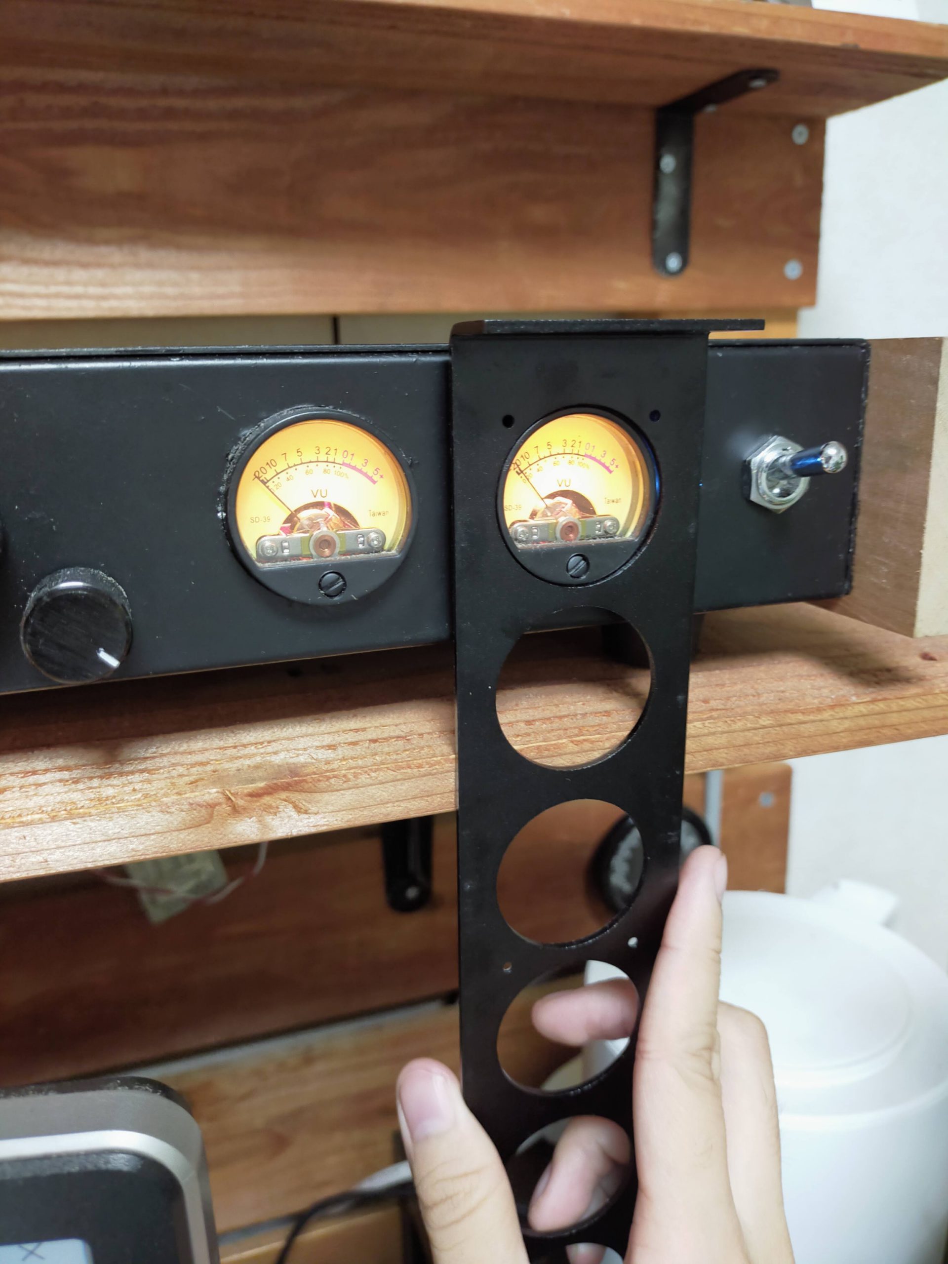
Especially in this case, there are 6 round holes with a diameter of 34 mm.
The speaker and VU meter were perfect size for GIXIE Case.
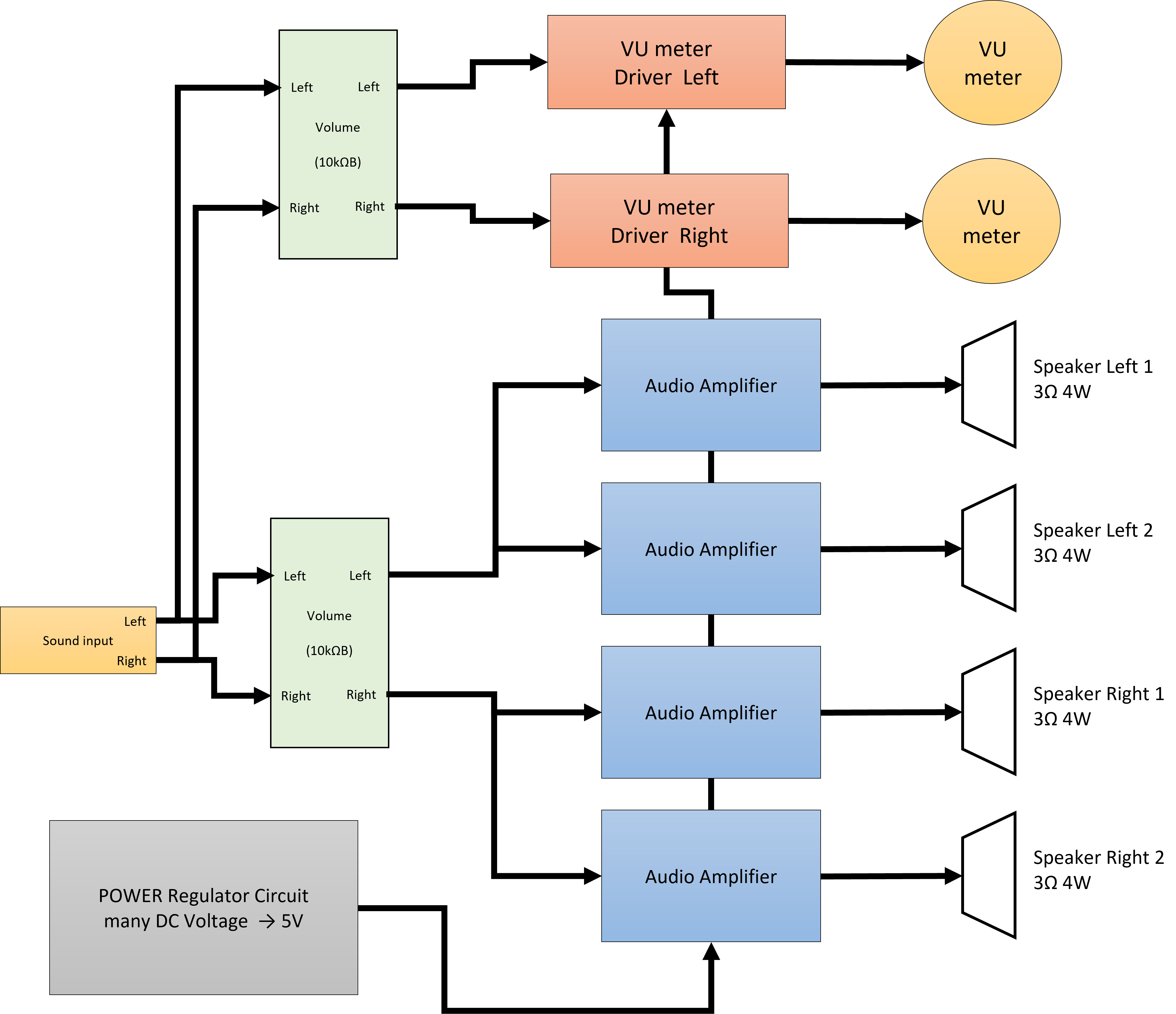
Therefore, I would like to make an audio amplifier speaker with 4 speakers and 2 VU meters.
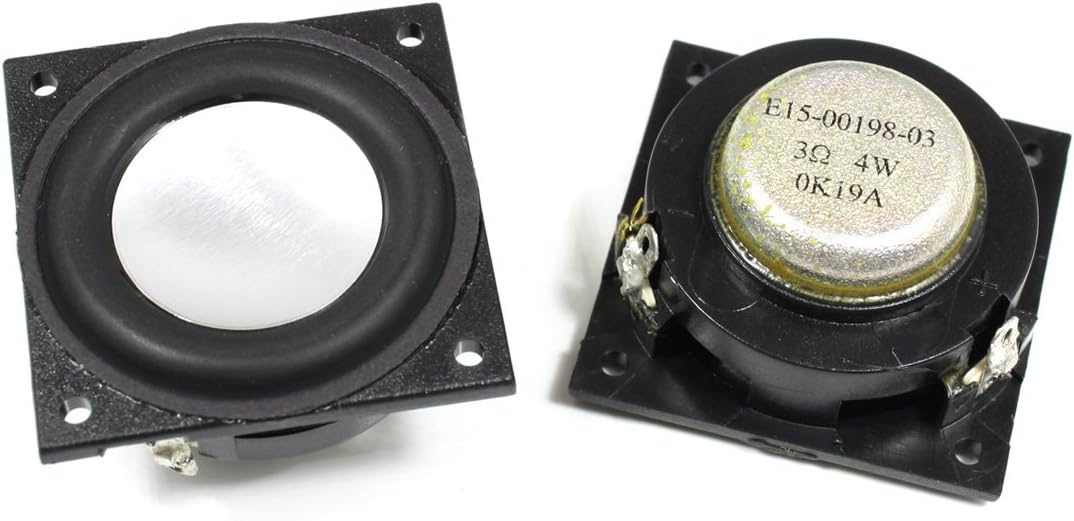
Select of Speaker Unit
This time, the size is small, so I didn’t ask for sound quality so much, so I decided to give priority to design.
Material: Plastic, electronic parts Header DC resistance: 630 ohms Backlight filament voltage: DC / AC 6V ~ 12V Filament backlit 500μ AVU meter It is widely used in audio recorder equipment
Block Diagram
The block diagram is shown below.
Since the impedance of a single speaker is low, it is difficult to connect speakers in parallel from a single amplifier. Therefore, you have to attach an amplifier to each.
Place two variable resistors in front of the amplifier and use this as a volume.
From the audio input, branch off from the amplifier and connect the VU meter driver in parallel.
Also, make it possible to input an arbitrary voltage with the DC jack, insert the regulator circuit, and supply it to each circuit.
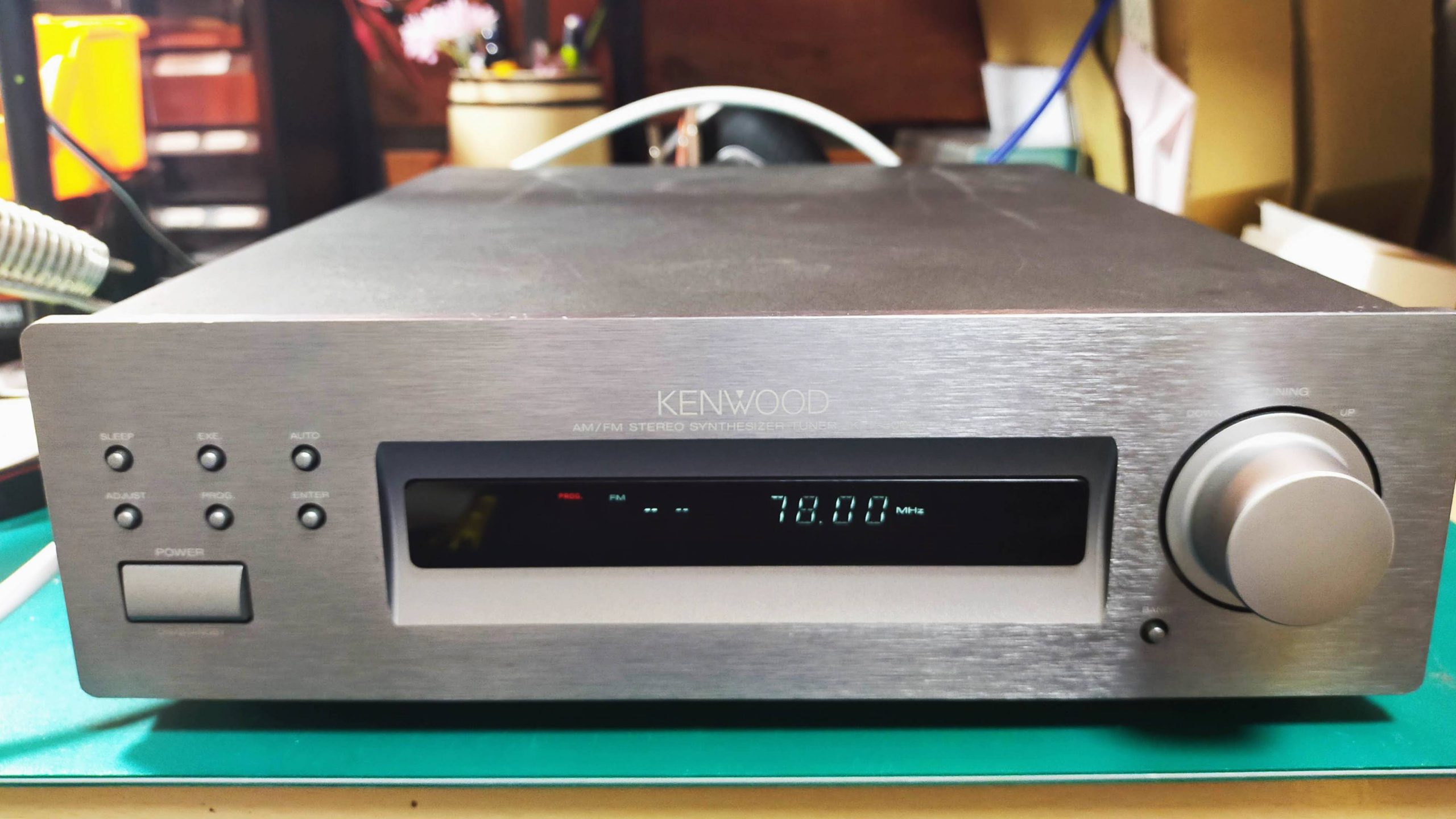
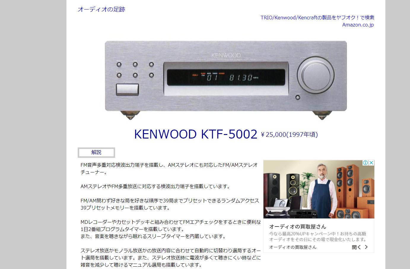
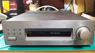
We are planning a new project from this time. Disassemble a commercial product and learn the technology hidden in it. This time, I will disassemble the AM / FM radio tuner, KTF5002 made by KENWOOD. This was sold at HARDOFF in the neighborhood for 1500 yen.
It was a junk item, but it was in good condition, and both FM and AM radios sounded fine.
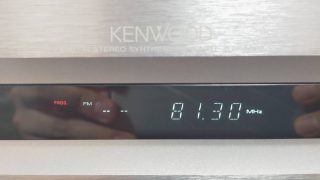
Can Receive FM radio
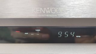
Can Receive AM radio
First of all, I investigated this radio.
When I looked it up, it was released around 1997. It’s one below from my age. The price is reasonable at 25,000 yen.
The pdf of the instruction manual was also included, so I will paste the link below.
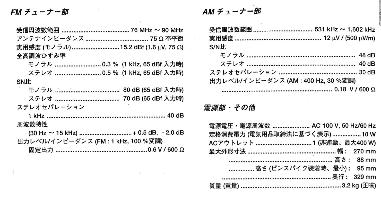
Reception frequency range of FM radio is 76MHz to 90MHz. It is enough range for FM radio at that time.
Over 90MHz was the band of analog TV audio signals. Currently, this vacant band is the complementary broadcast of AM radio (WideFM).Total harmonic distortion is 0.5%, which is reasonable for audio equipment.
What surprised me personally was that the SN ratio of the FM radio was 70 dB. I think the performance is quite high for that time.
In addition, the SN ratio of AM is 40 dB. After all, AM radio has more noise than FM.
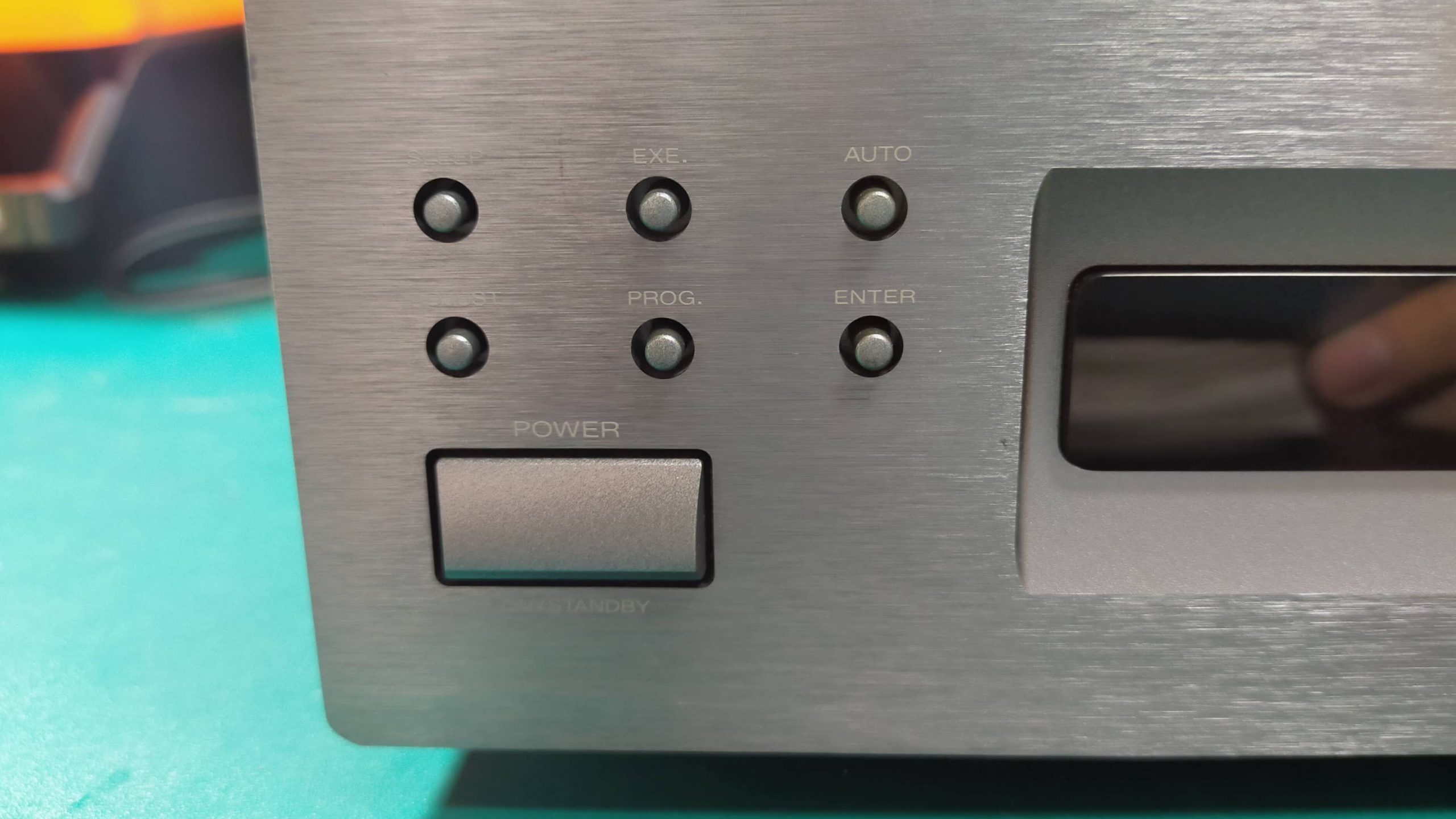
Front panel
It seems that you can set Auto (automatic tuning), sleep, time reservation, etc.
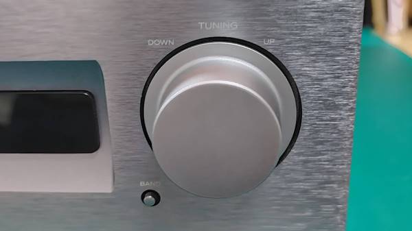
At first glance, I thought it was a volume, but this is a channel selection. You can’t spin it around, just tilt it.
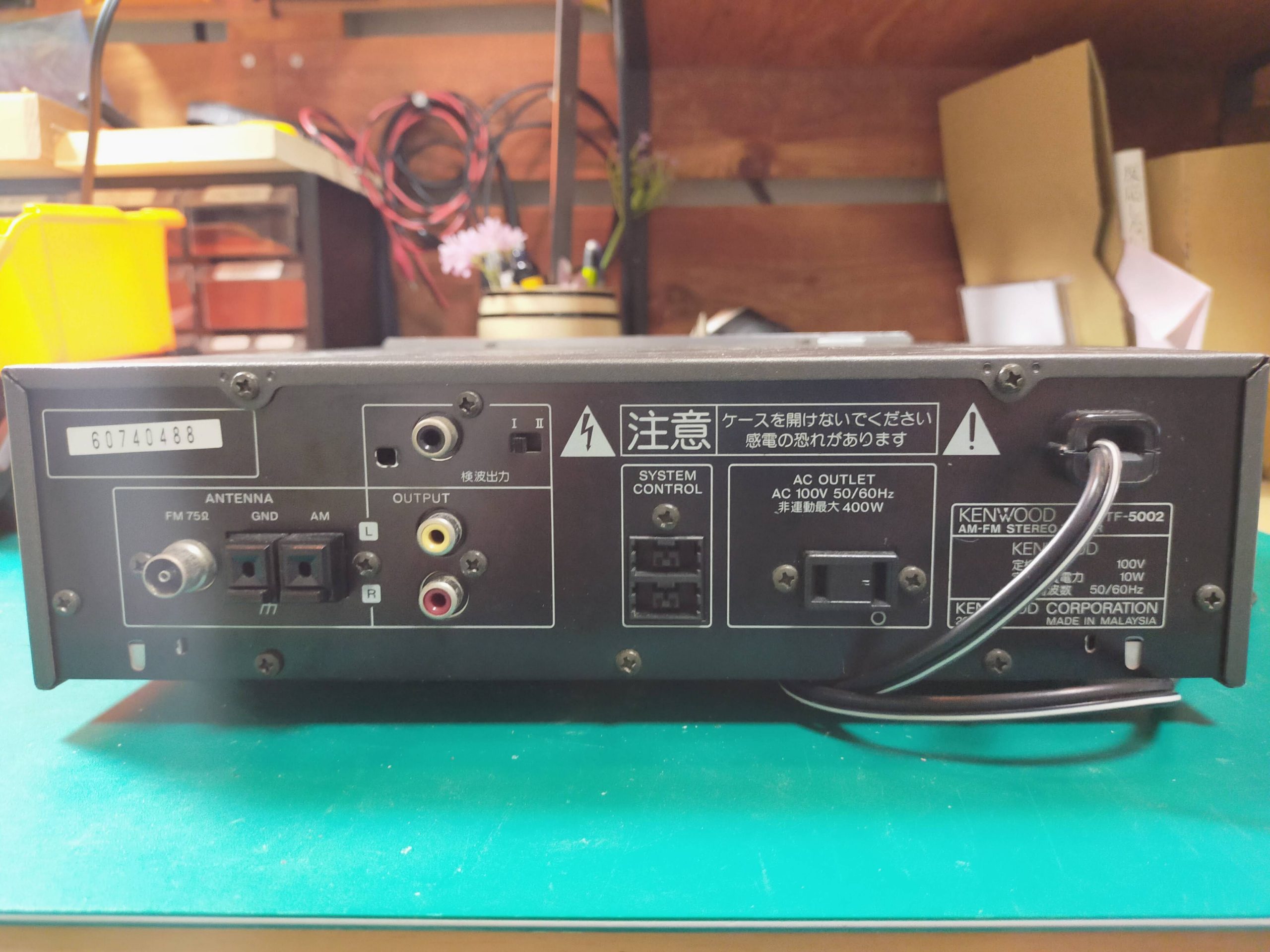
The back is like this. There are FM antenna terminal, AM antenna terminal, audio output, outlet, and detection output. The FM antenna terminal is the same as the TV antenna wire.
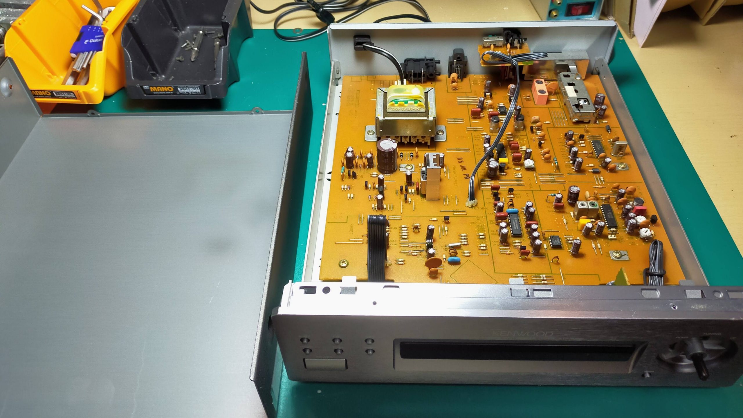
Let’s remove the cover and take a look at the contents.
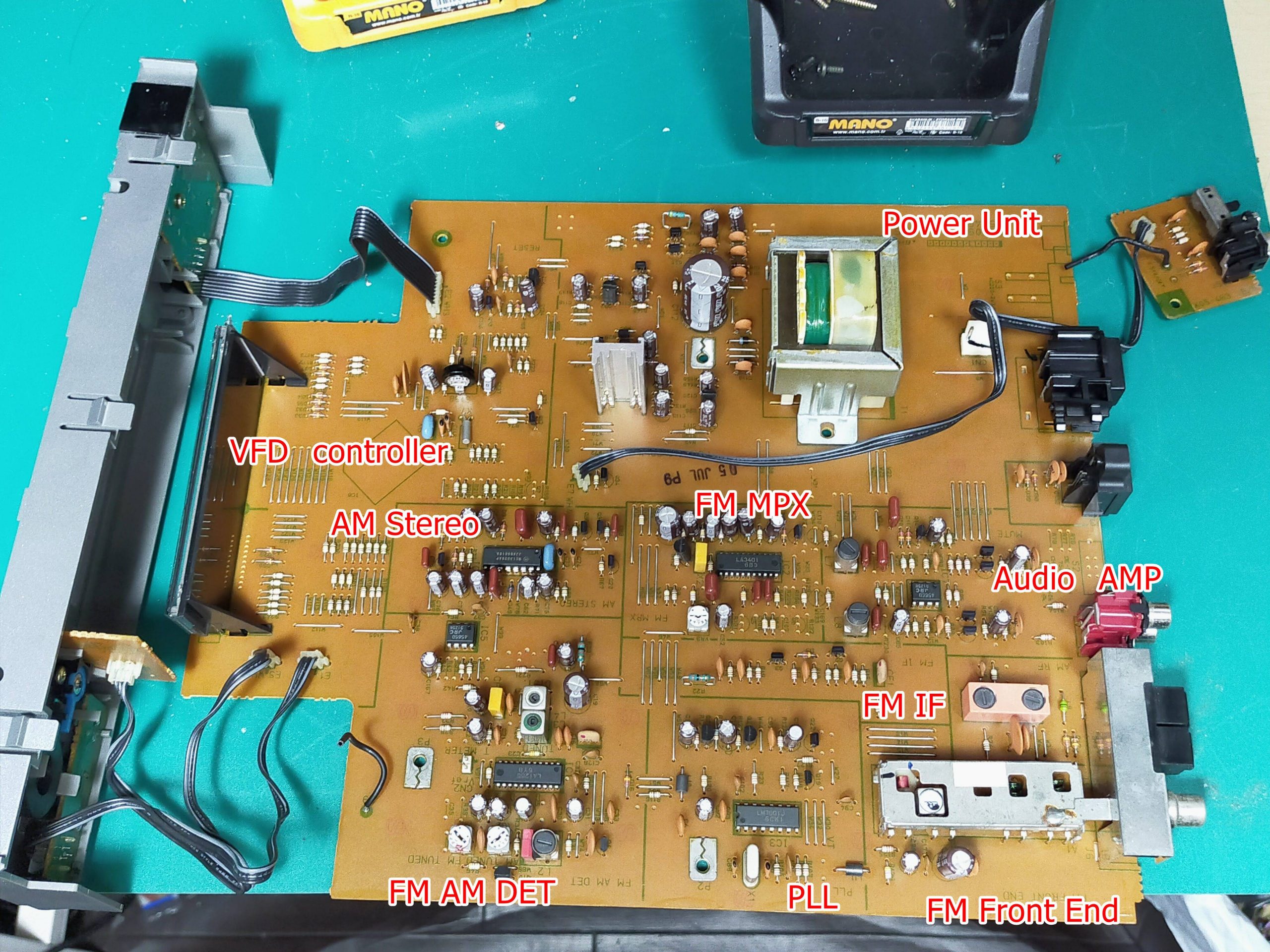
I see. I thought it was complicated, but the contents were contained in one board. Take out the board further. Roughly, the name of the circuit is shown. It consists of many circuits such as FM front end, FM multiplexer, AM stereo demodulation circuit, PLL circuit, power supply circuit, etc. I will explain these circuits one by one in future blogs.
Today, I just disassembled it, so I will focus on the entire board.
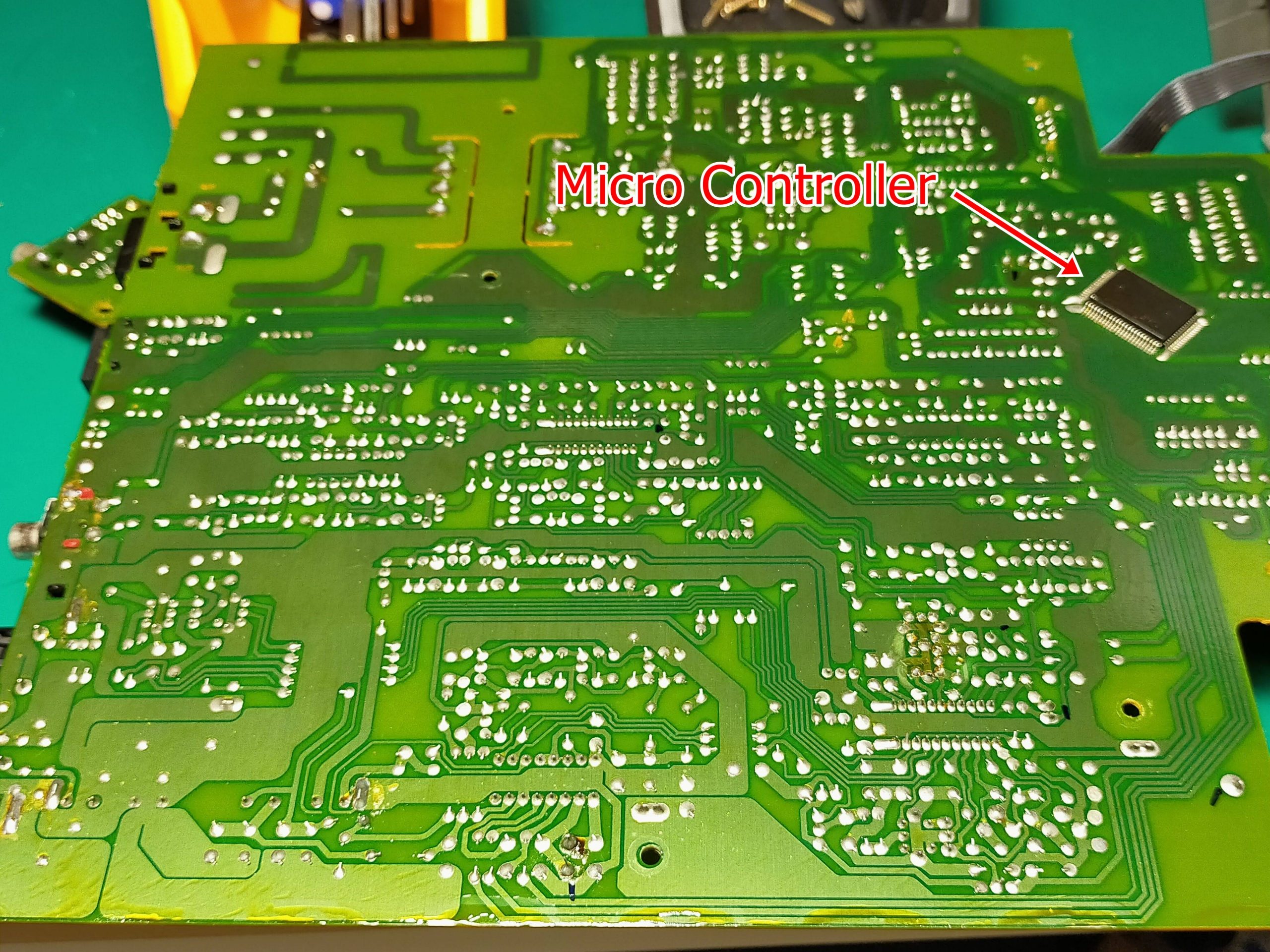
First, the material of the substrate is a paper phenol substrate. It’s cheap and not very durable, but it’s good enough for stationary audio equipment. The board has a one-sided single-layer structure, and the parts are attached to only one side. Therefore, jumper lines are often used because of the intersection of lines. In addition, the surface mount components are only the microcomputer (thick, …) attached to the back surface, and all the rest are discrete components. All of this part is manually inserted, where the legs of the part are bent behind the board. And you can see that it is cut by human hands.
Also, since there is no unevenness in the soldering, it can be seen that the board is applied to the solder bath and the soldering is done by the flow method. Only the microcomputer may be retrofitted and reflowed with cream solder.
Honestly, I think that this is a considerable labor cost from the current era.
I think it’s amazing that this is sold for 25,000 yen.
Also, the power supply circuit is also noteworthy.
Audio-related equipment is so heavy because it does not use a switching method in the power supply circuit. Switching power supplies are, for example, mobile phone chargers and personal computer charging adapters. If you use switching, the circuit of this radio will be lighter, but switching will generate a lot of noise, so if you use it as a power supply for the radio, the SN ratio will drop at once. Therefore, there is no choice but to place a large transformer and make it with an old-fashioned power supply circuit.
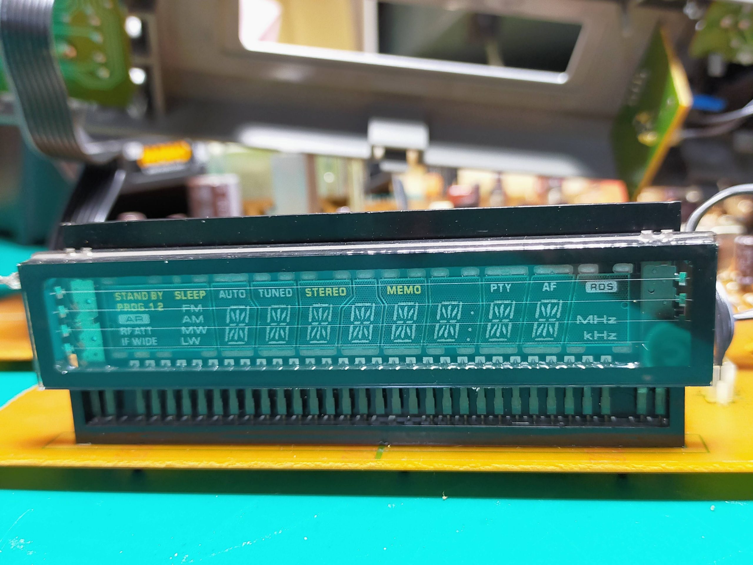
In addition, the display is a display method called VFD. Often, at the supermarket cashier, the pale letters “Gokei 2350 En” appear. Nowadays, there are many liquid crystal displays (calculators, etc.) and LEDs, but this is an old-fashioned display that applies vacuum tube technology.
I hope I can write this in detail in future blogs.
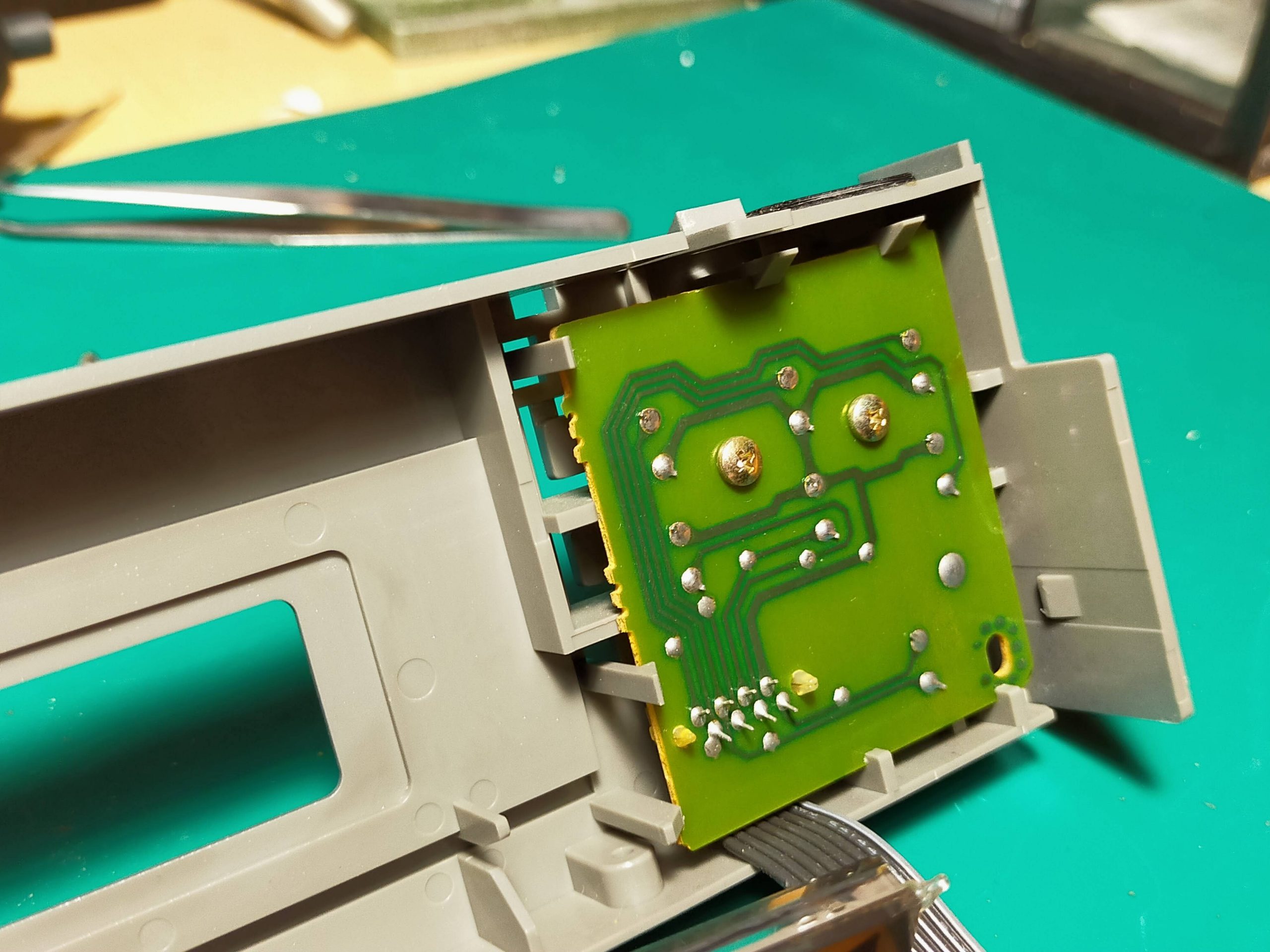
Finally, the back side of the switches. It was pretty simple.
Today was a roughly disassembled report. In the future, I would like to analyze this product in more detail with the following plan. Next time, I will explain the reception principle of AM radio and FM radio on 9/2. I will also touch on the story of PLL and MPX.
Current serialization; “Disassembly survey of FM / AM stereo tuner KTF-5002”
Update
Content
8/26
I disassembled KTF5002 (specifications, disassembly procedure, board configuration, mechanism)
9/2
AM / FM radio reception principle (AM / FM is the main reception method used, what is PLL / MPX)
9/9
I investigated the IC used in KTF5002
9/16
About FM front-end circuit, FM-IF circuit, AM-RF circuit
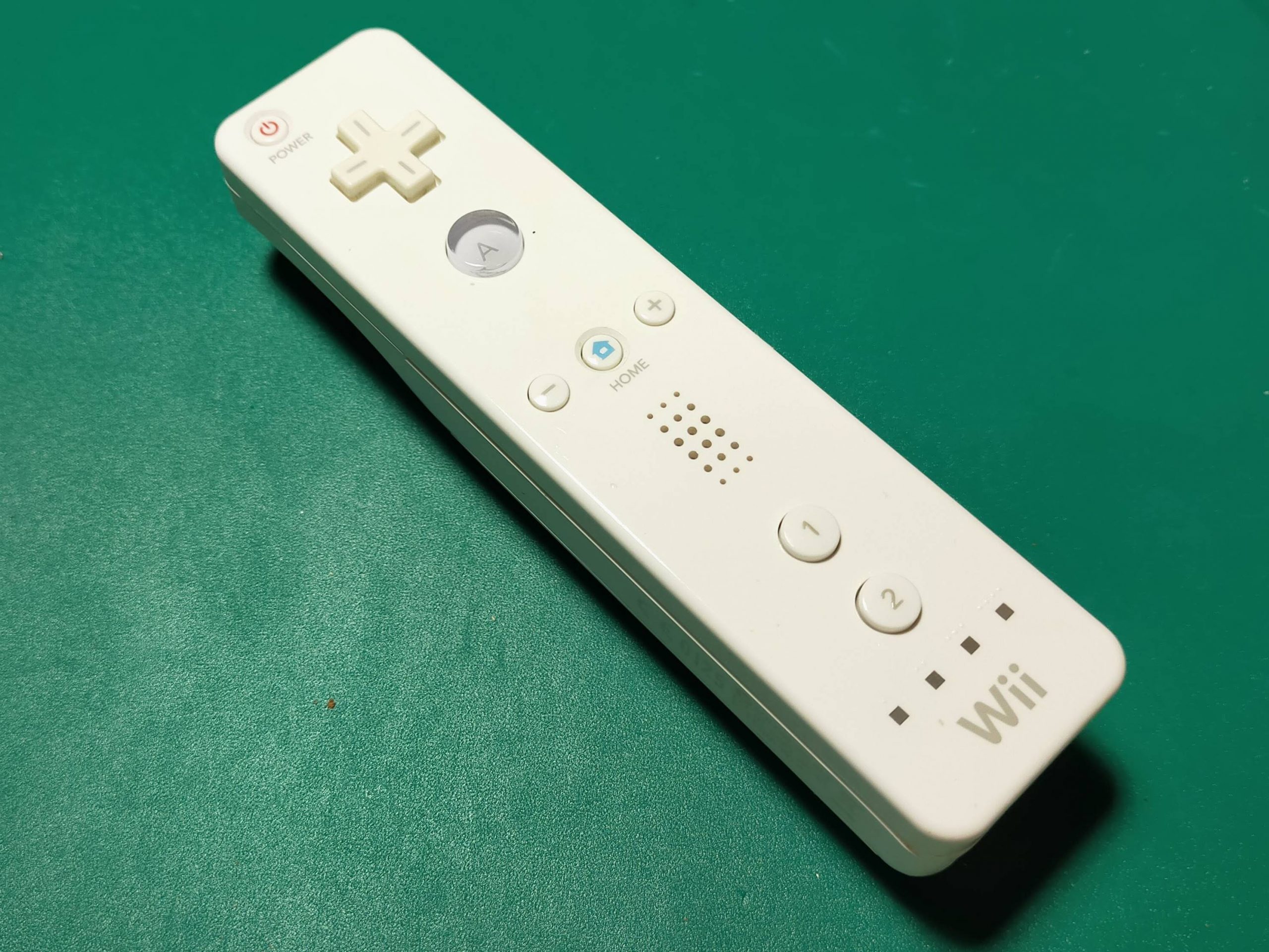
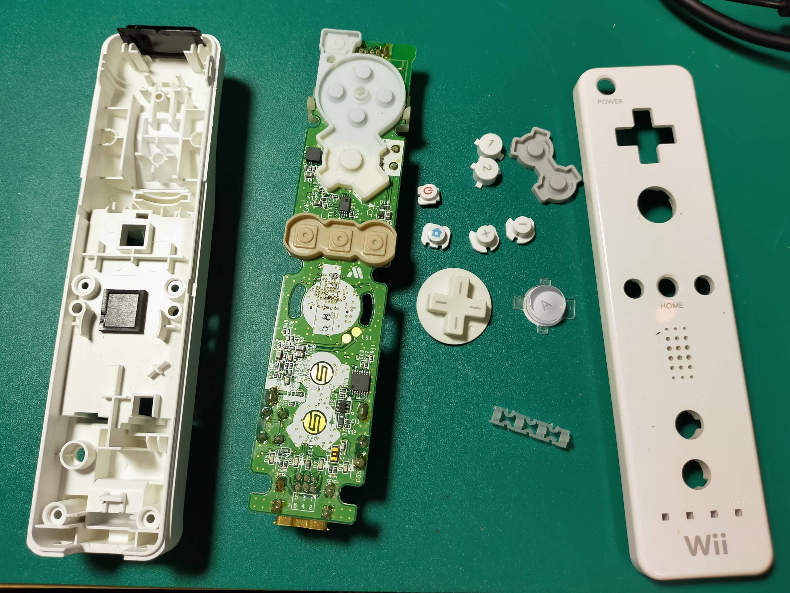
This time, I disassembled the wii remote controller. Wii was very popular at one time, but do you all remember it? Now, it is sold at Hard Off for 300 yen. I decided to disassemble it because it was a big deal.
I will open it immediately.
I see, I wonder if it’s like this. After all, speaking of wii, it detected the tilt and shake of the remote control, height and horizontal movement. Where is that sensor? Let’s take a closer look.
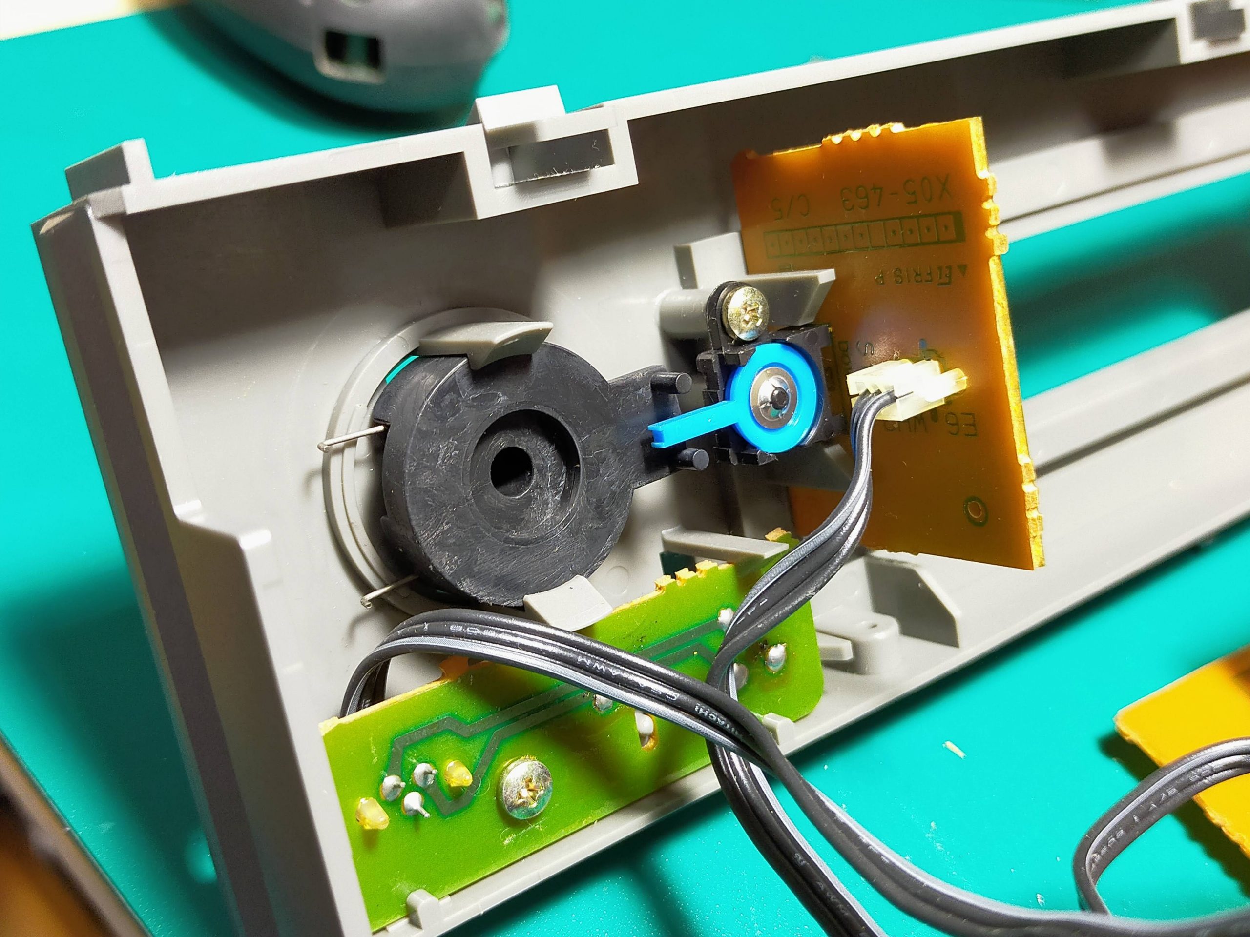
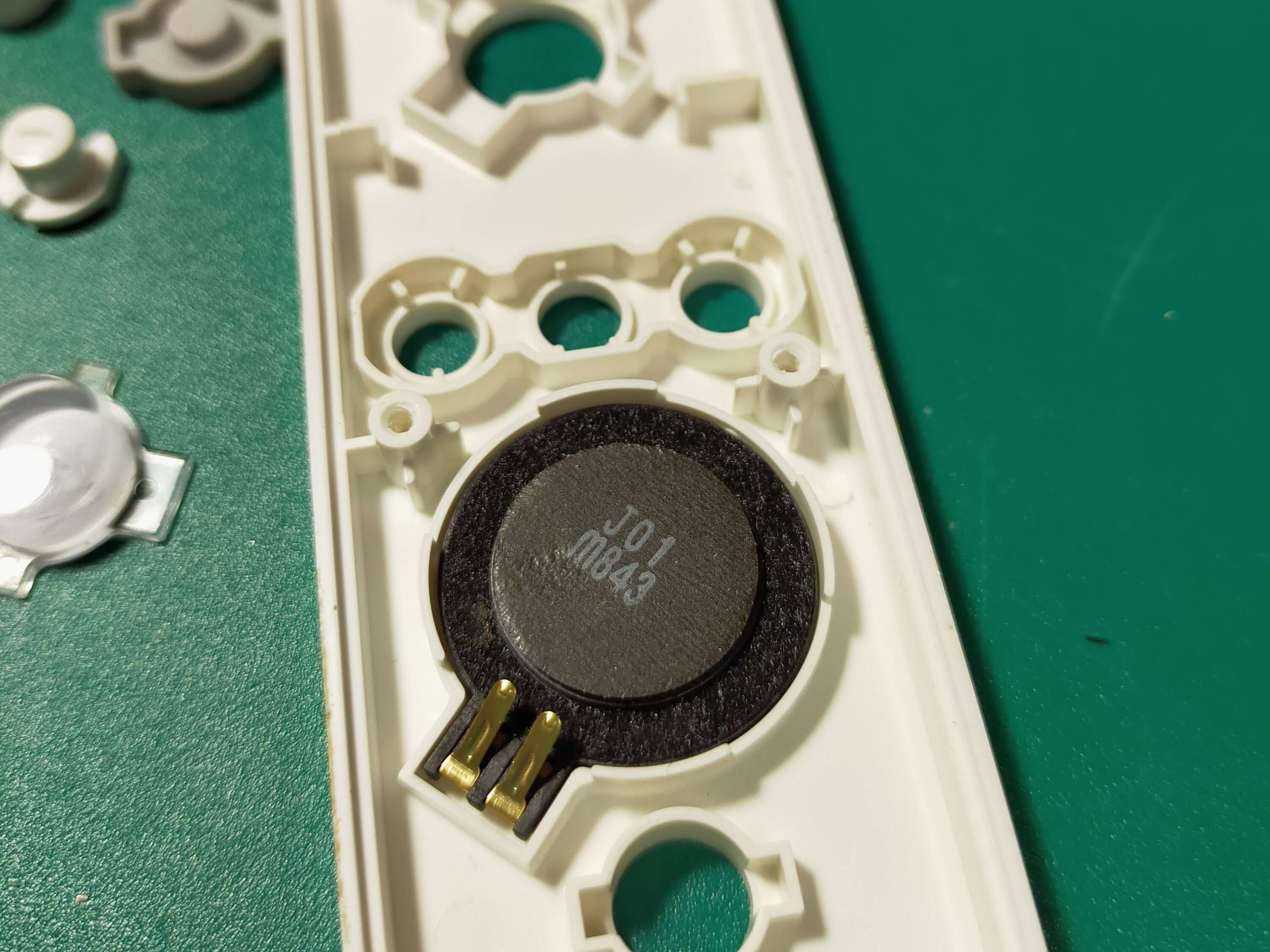
There was a speaker on the back side of the top of the main unit.
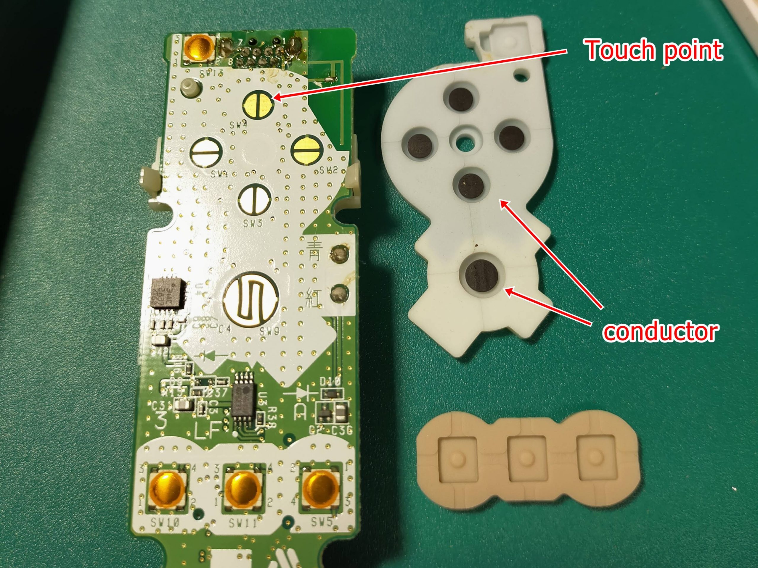
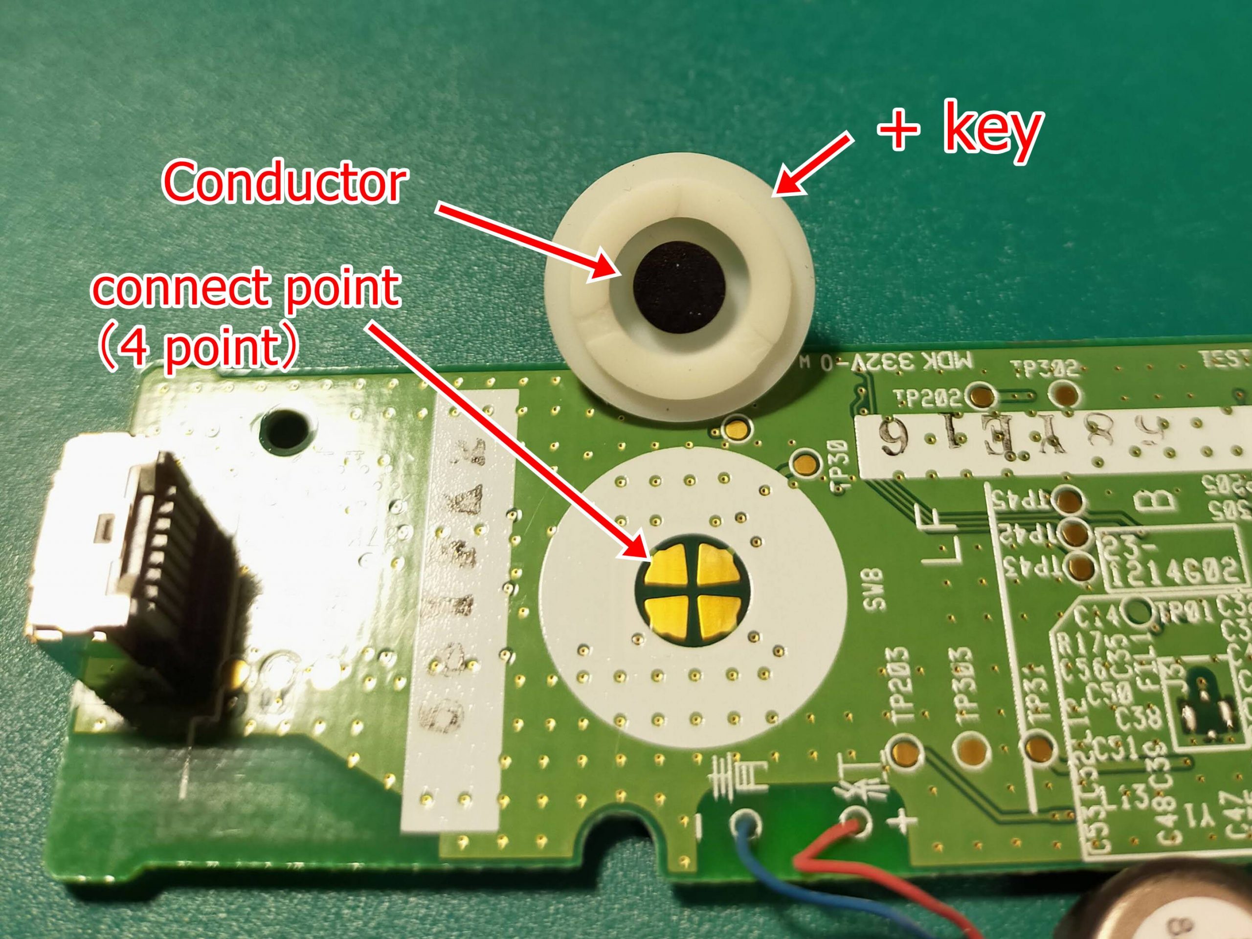
I see, the area around the buttons is very simple. A silicone button with a conductor attached to it acts as a button by hitting the contacts on the board.
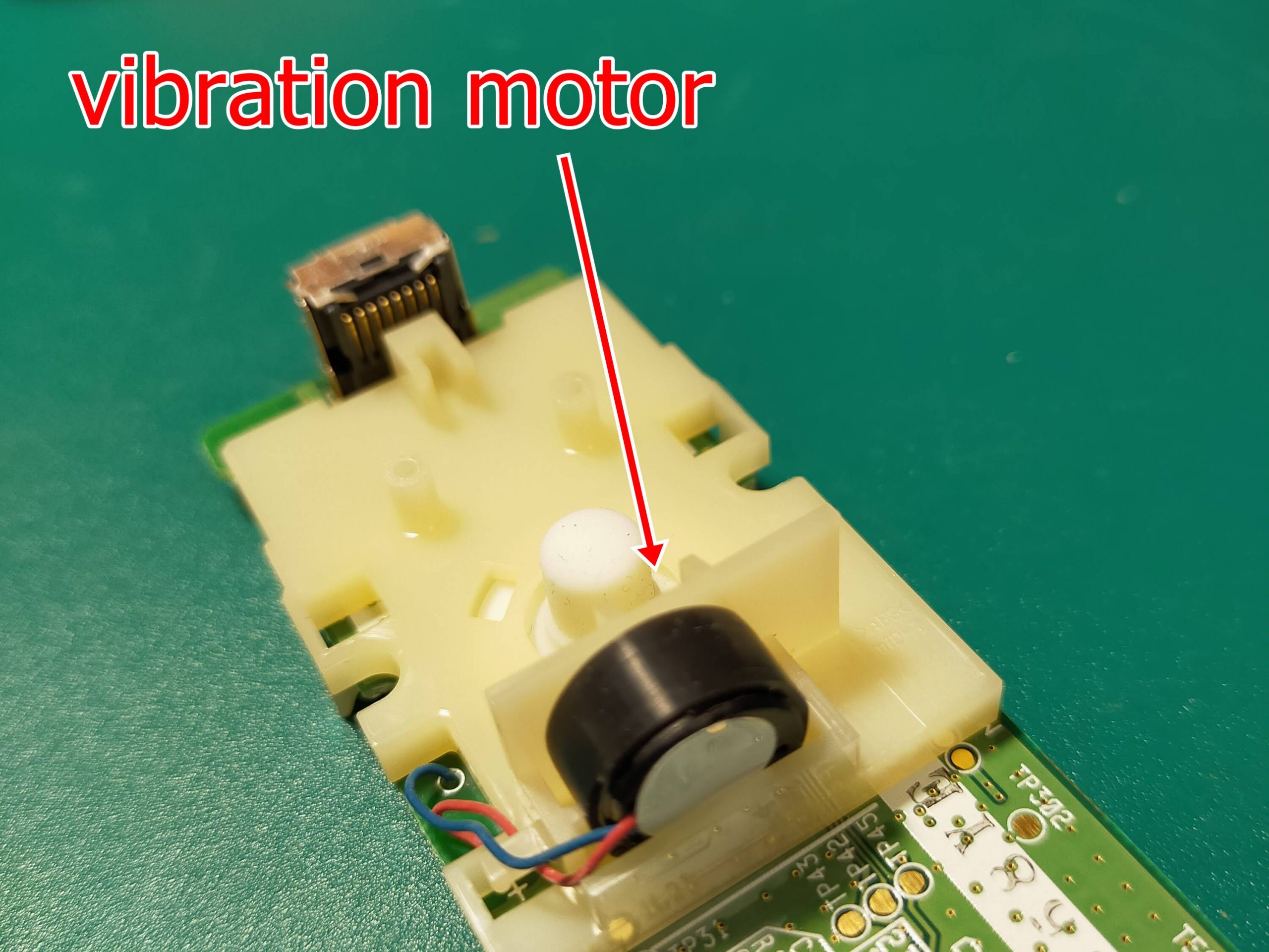
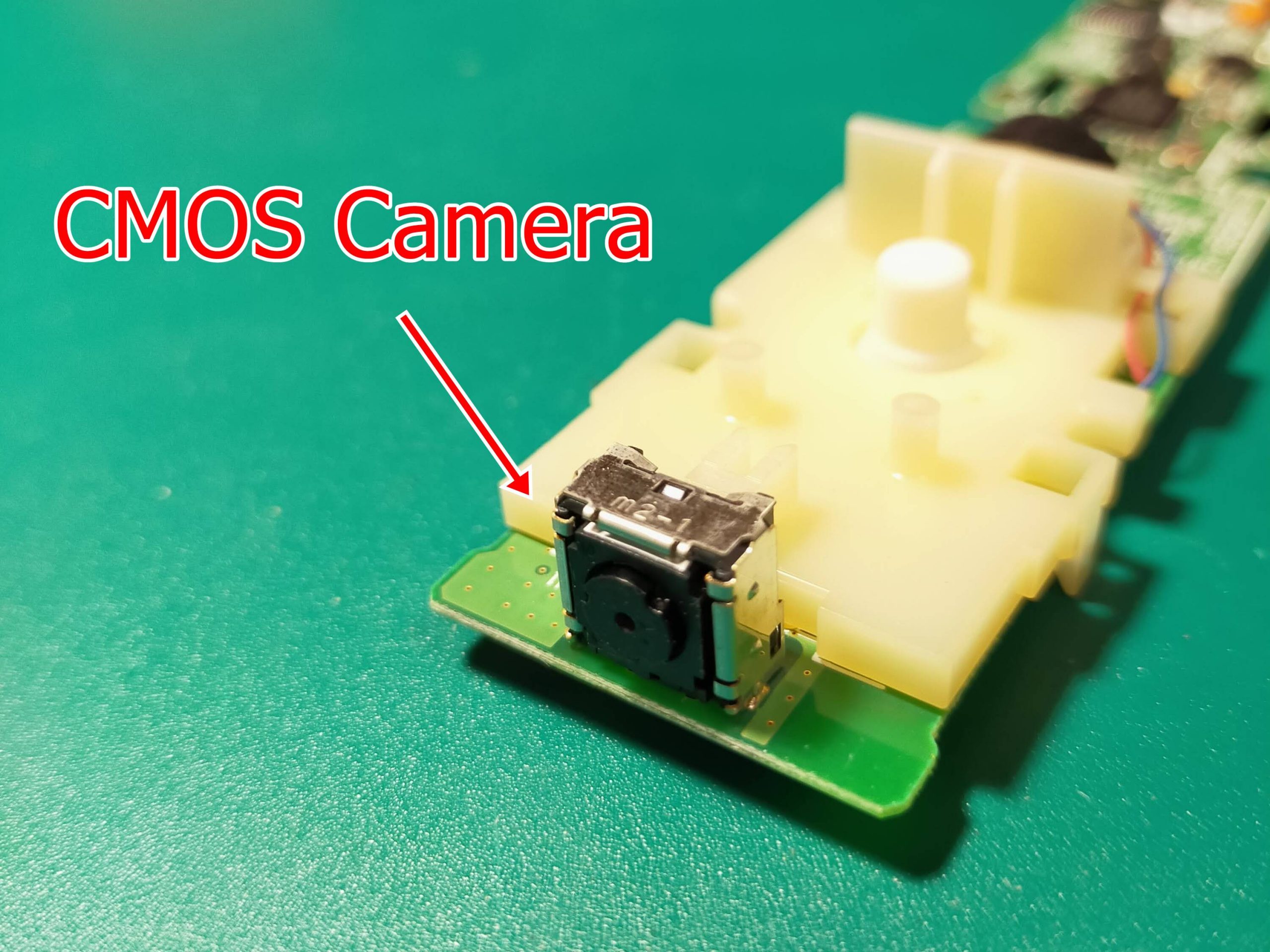
After that, there was a vibration motor and a CMOS camera in front. I see, did you see horizontal movement with this camera?
The cross button in the middle has four conductors. .. ?? I thought, but it was one. Also, there are four contacts. It seems that the direction of the cross is determined by which contacts are connected to each other.
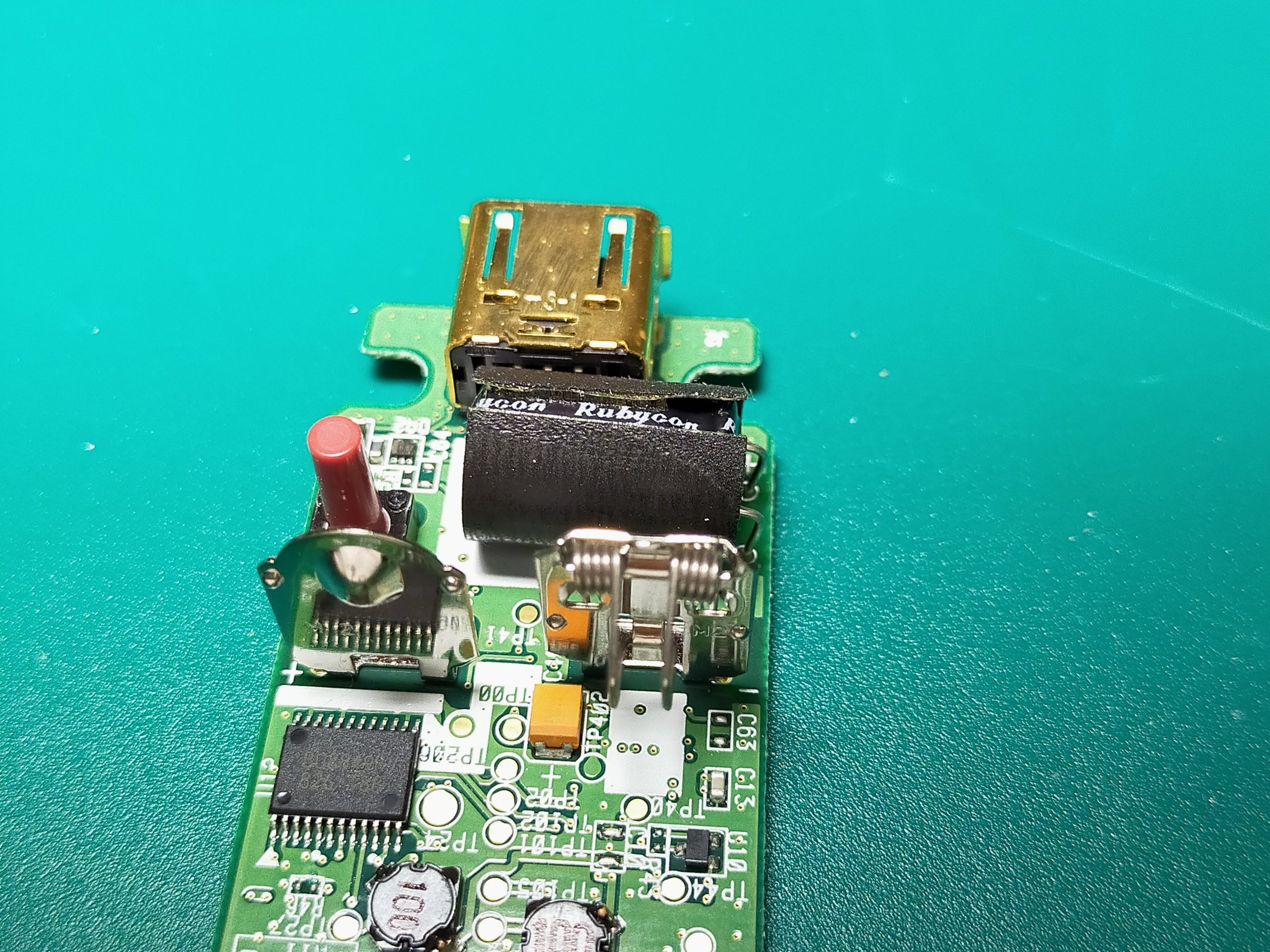
The connector that connects the Joy-Con was gold-plated.
In addition, the input of the power supply contains an electrolytic capacitor made by Rubycon.
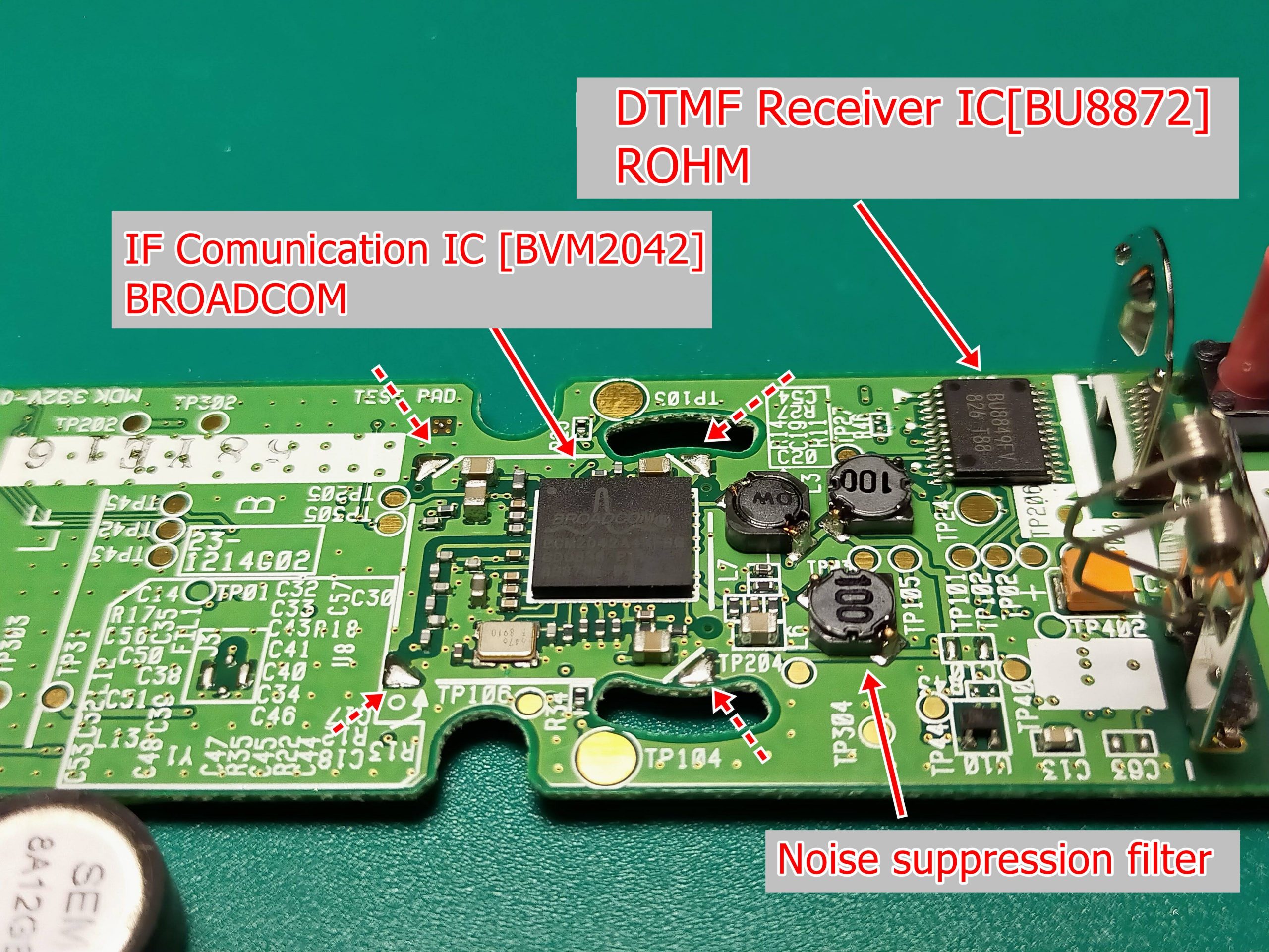
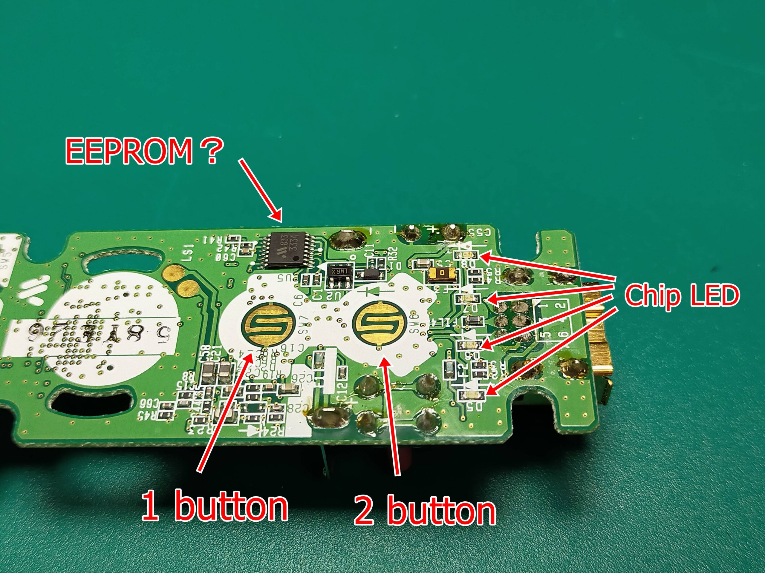
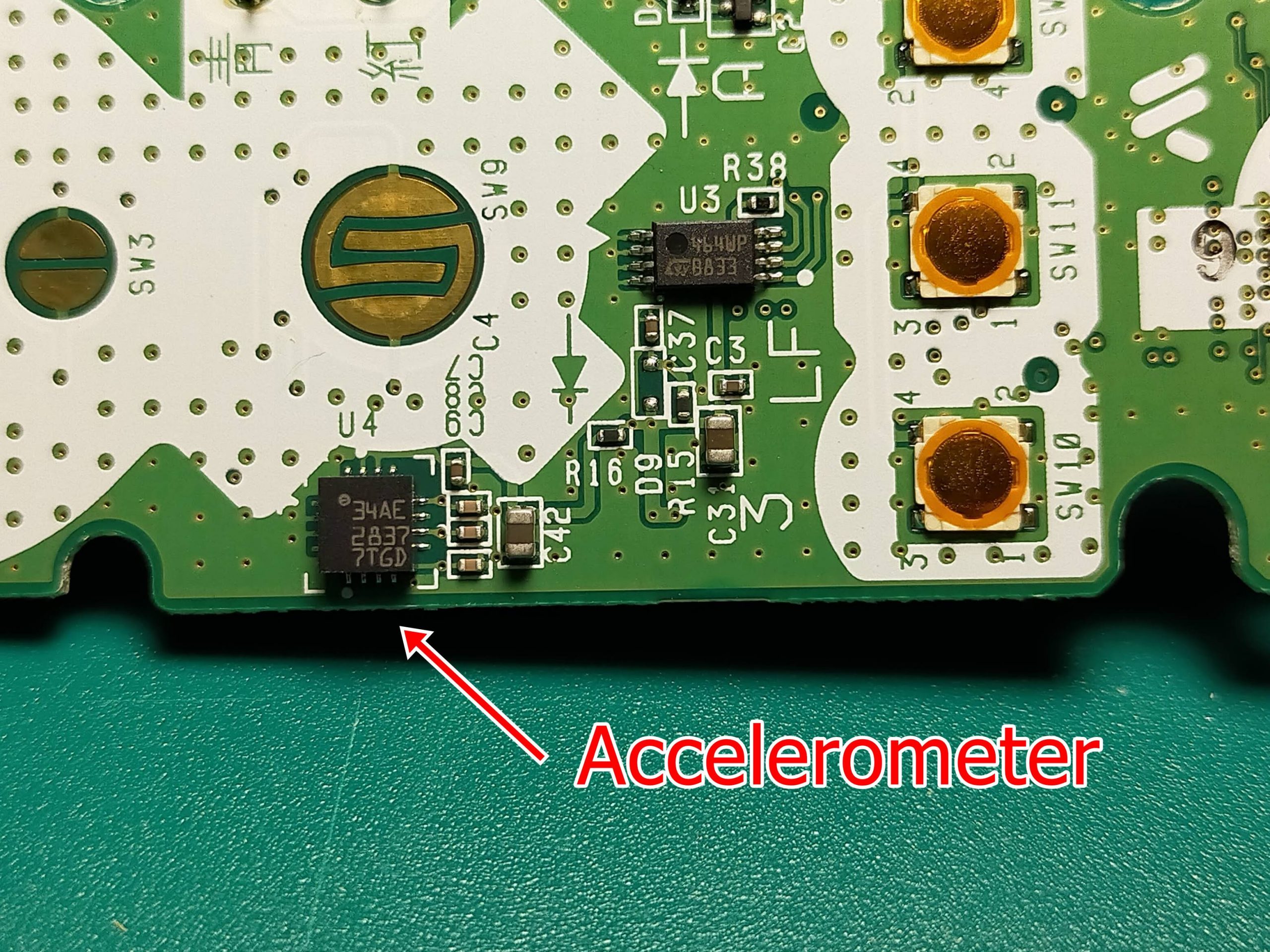
On the back side of the board, a DTMF receiver IC (BU8872) for communicating with the joystick, an IC for wireless communication with the Wii main unit, and BCM2042 made by BLOADCOM are mounted. In addition, there were triangular pads at the four corners of BCM2042.
Probably this is a pad to put a metal cover here when the noise test goes wrong.
It is probably not implemented because it has good noise immunity.
Also, there was something like EEPROM on the surface. It’s like memory for storing data. I remember the minimum operation.
There was also an accelerometer on the upper side of the surface. This is detecting the tilt of the wii remote controller.
Also, in the near future, I would like to investigate these IC chips and make a blog.
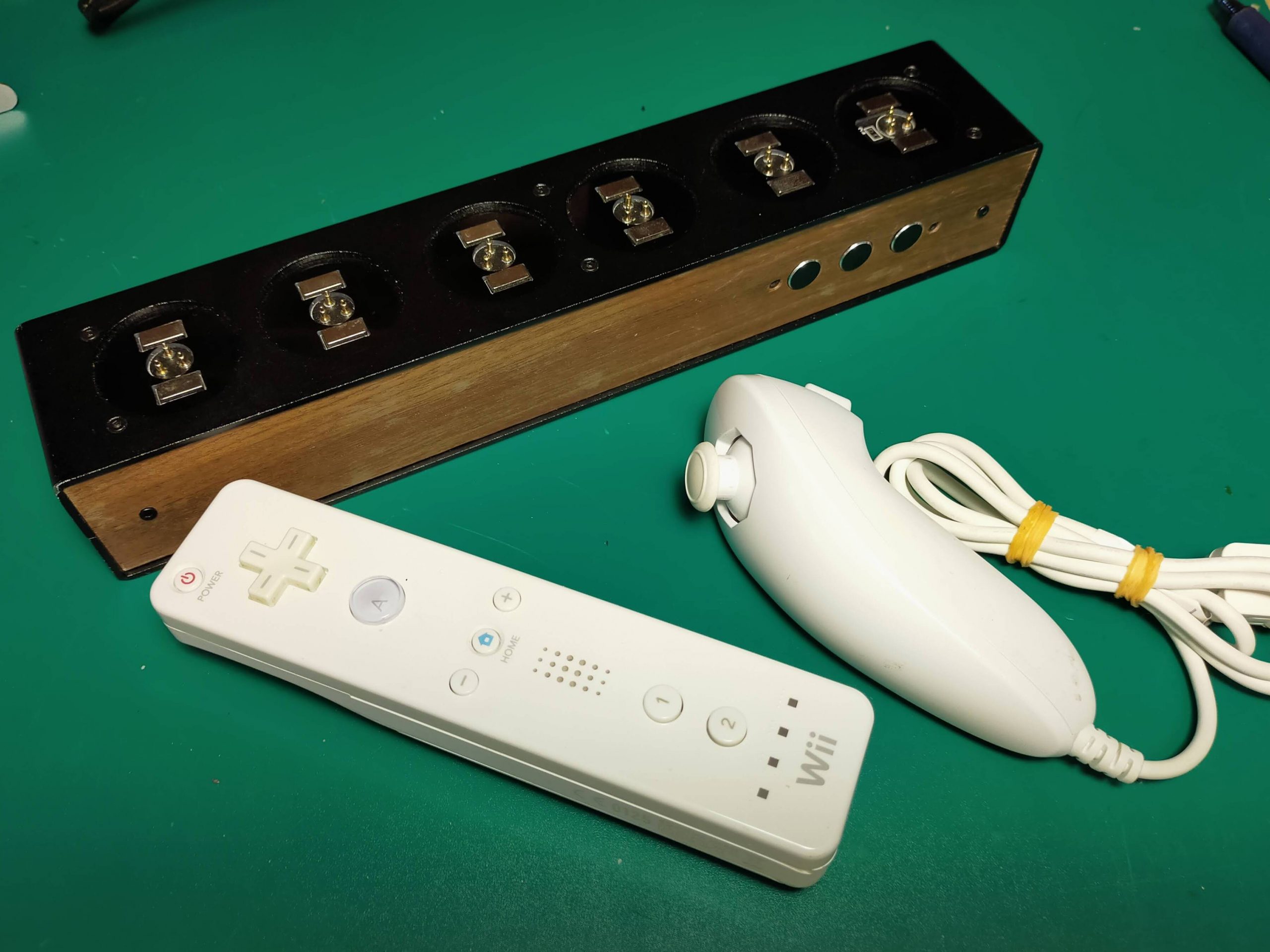
The day before yesterday, I went to Hard Off in my neighborhood and bought an unfamiliar box and a wii remote controller on impulse for disassembly.
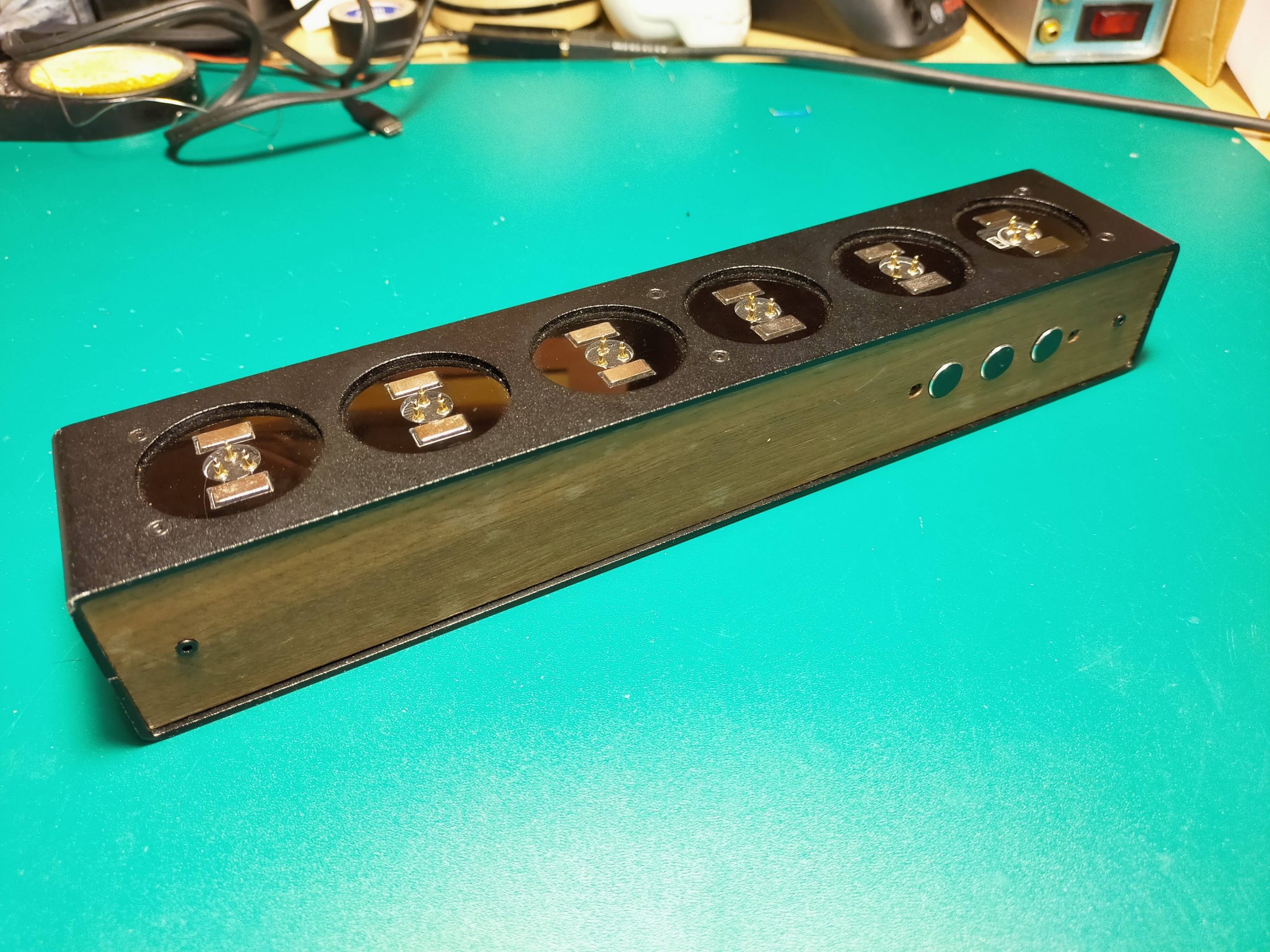
This time, I will confirm the identity of this mysterious wooden box.
Even if I don’t know what’s inside, I thought this case could be used in many ways.
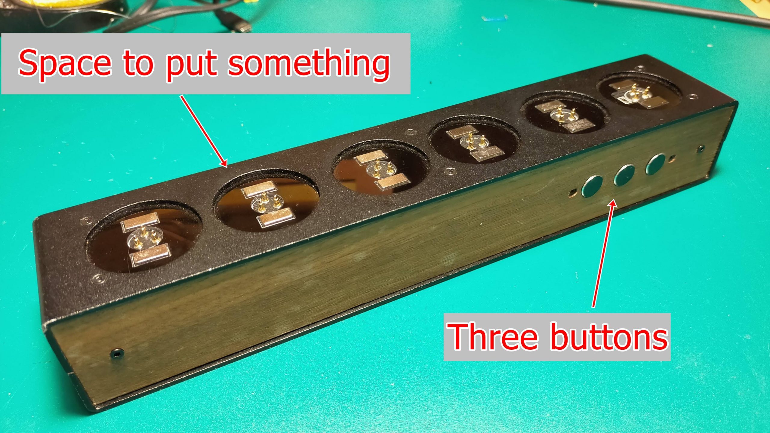
First of all, there are 6 spaces on the top where you can put something.
And there were three buttons next to it.
The place to put something was two magnets and three terminals in the middle.
Two hypotheses are possible, one is that these two magnets are + and-of the power supply, respectively, and the middle three may be signal lines (three are SPI communication). I have.
Another hypothesis is that no voltage is applied to the magnet, two of the three terminals are + and-of the power supply, and the other one is the signal line. If there is not a lot of data (7 segments, etc.), I think that there is no problem with control like a servo motor.
The back side only has a DC jack.
The voltage is not written and I am scared so I have not applied the voltage yet. The DC jack is a 2.1φ one sold in Akizuki, so it feels very close to you.
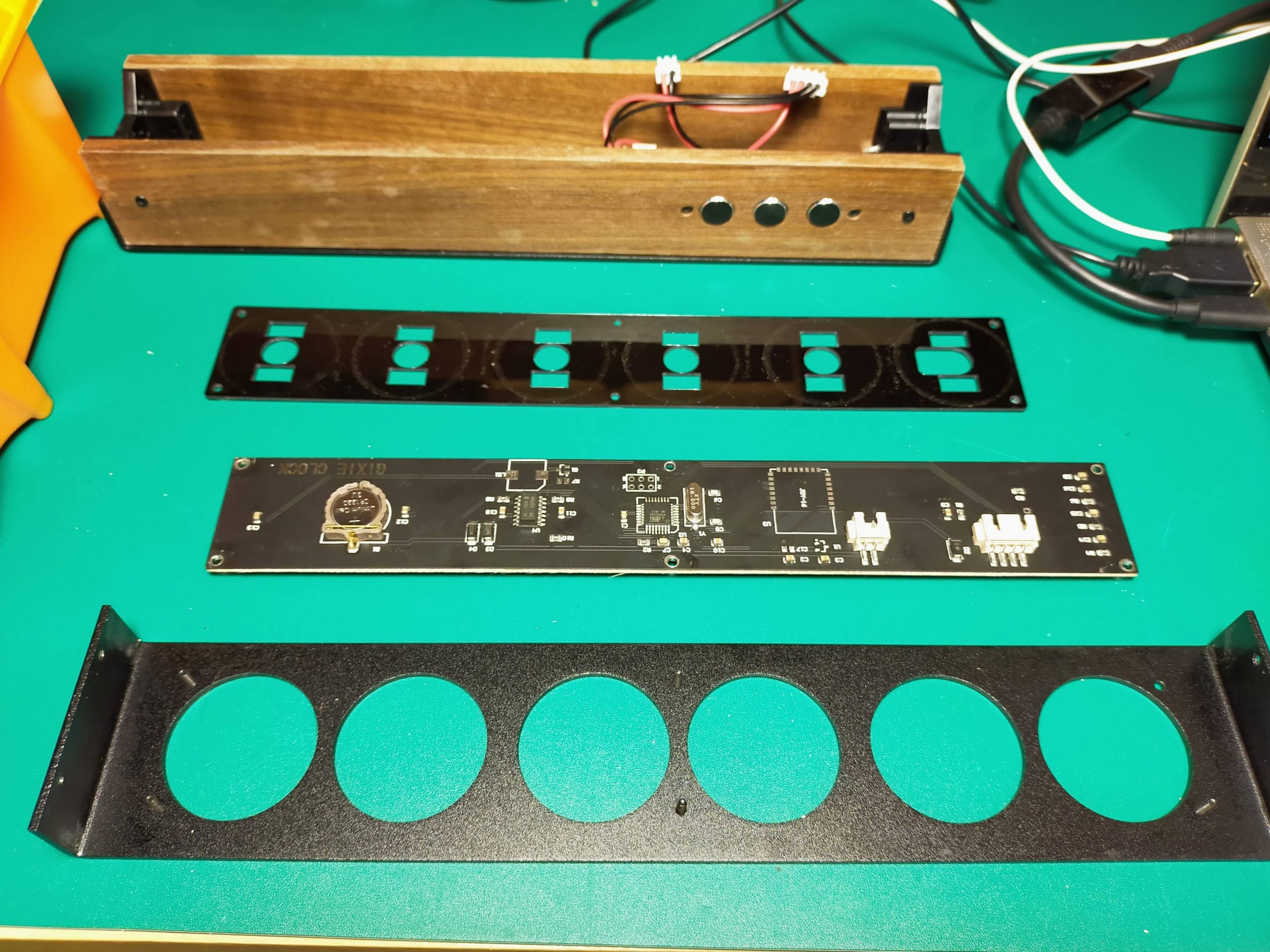
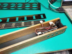
Let’s open the inside now.
! !! !! !! !! !! !! !! !!
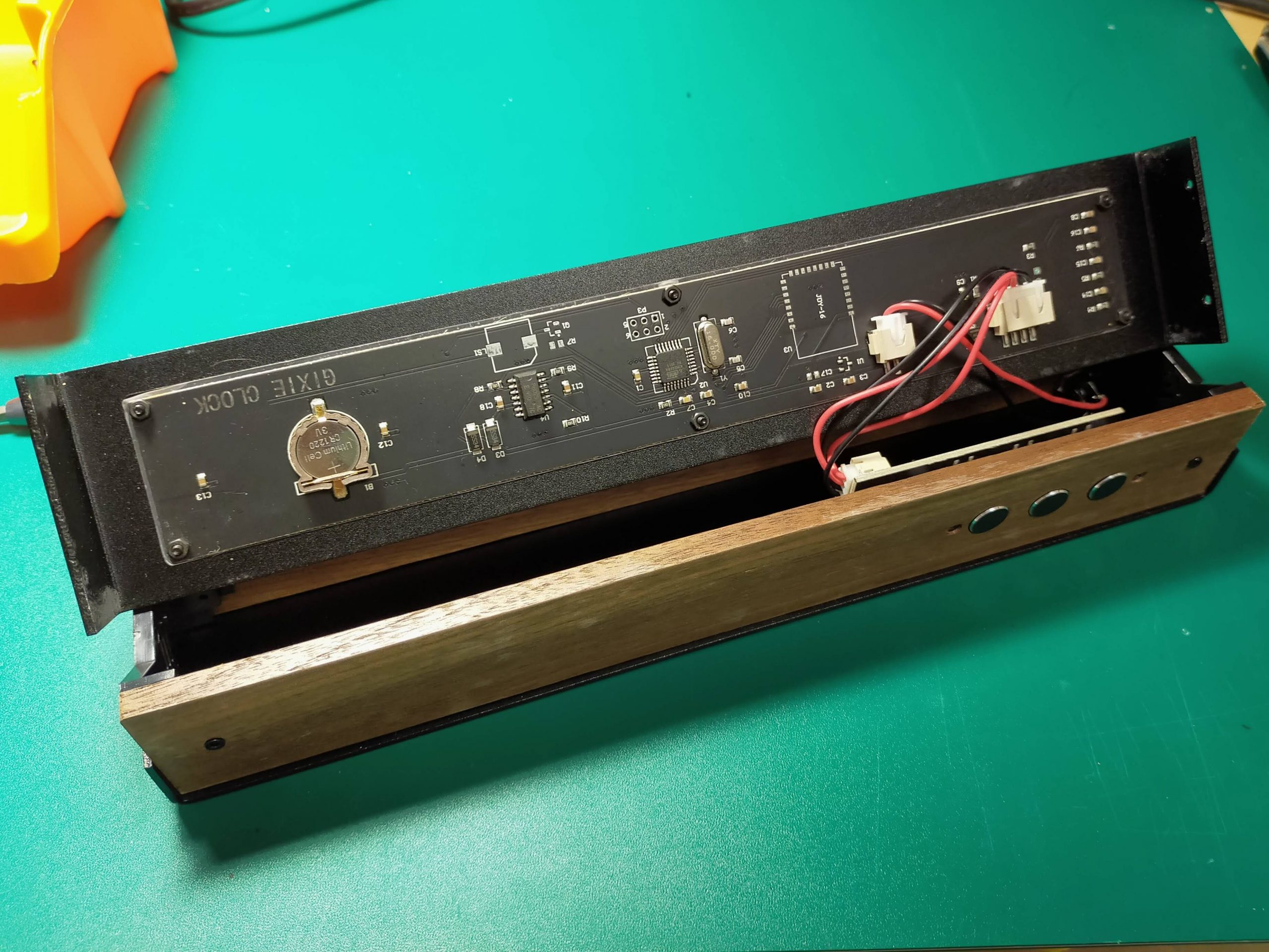
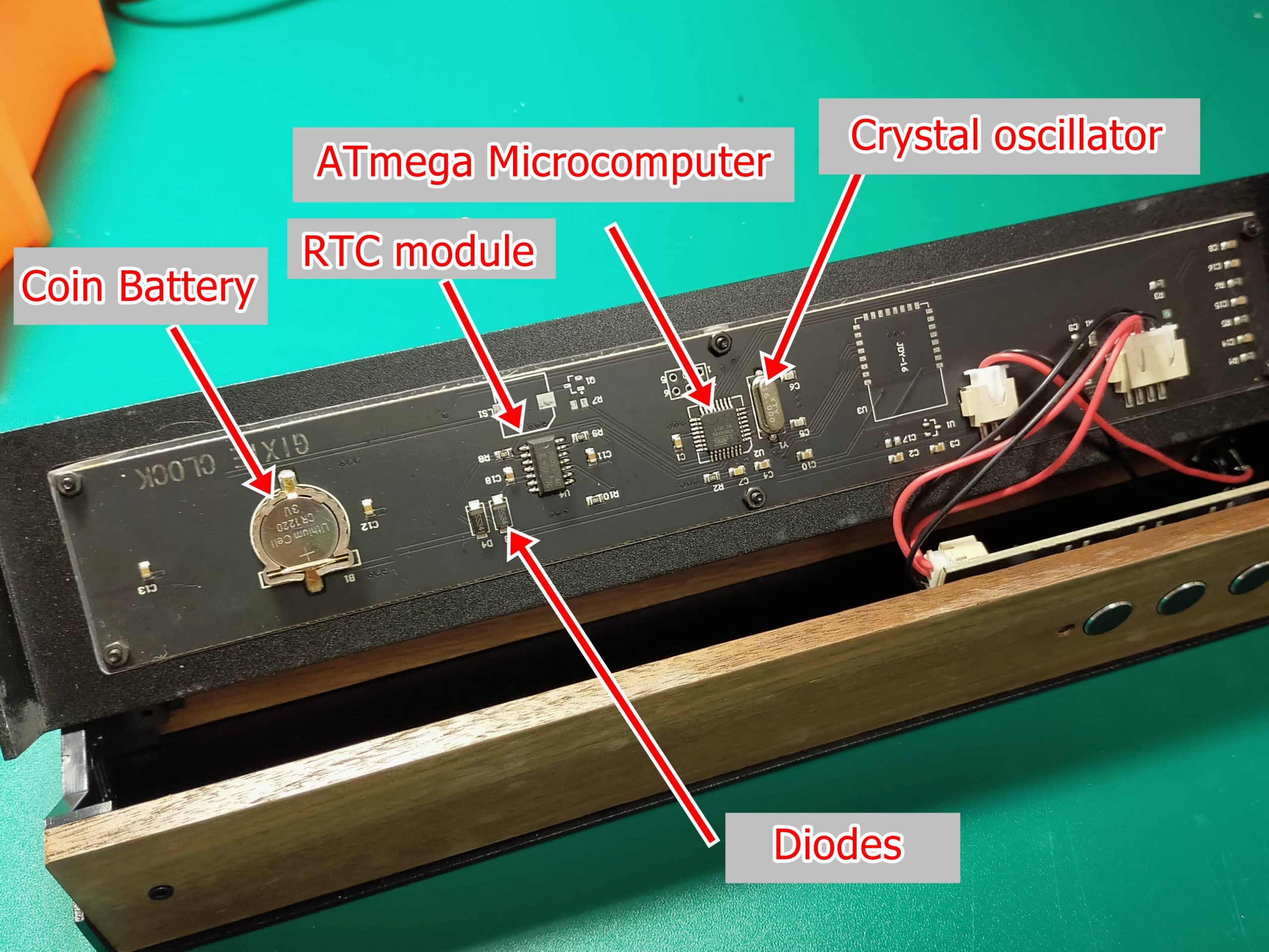
It was very simple inside. First, there is a microcomputer, a crystal, and a coin battery in the middle.
Let’s take a closer look at the board.
First, from the board, this is a clock.
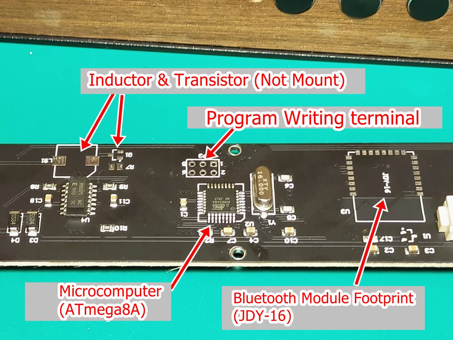
The microcomputer chip that controls the display system uses ATmega8A, and a 16MHz general crystal oscillator is used for the clock. Also, I think the chip next to it is the RTC (real-time clock).
This is an element that keeps ticking the time accurately and keeps sending the data of the current time to the microcomputer. Even if the power is removed, coin batteries are loaded so that the time can be kept ticking with the least power consumption. The voltage of the coin battery is 3V, while the voltage supplied from the power supply is 5V, so the voltage of the power supply does not flow into the coin battery and the voltage of the coin battery does not flow into the microcomputer etc. There are two.
There were also unmounted parts. First, the 6-pin terminal next to the microcomputer is the program writing terminal. You can easily rewrite the program by connecting it to the ISP terminal of Arduino.
Also, I am concerned about unmounted parts. Especially, the unmounted terminal written as JDY-16 is worrisome. This is a Bluetooth communication module. Perhaps it is for connecting to a smartphone etc. and making the watch such a thing or something like this. I wonder if there are some options. I do not know.
I checked it because it was written on the board as GIXIE CLOCK.
It seems that I got something more amazing than I expected.
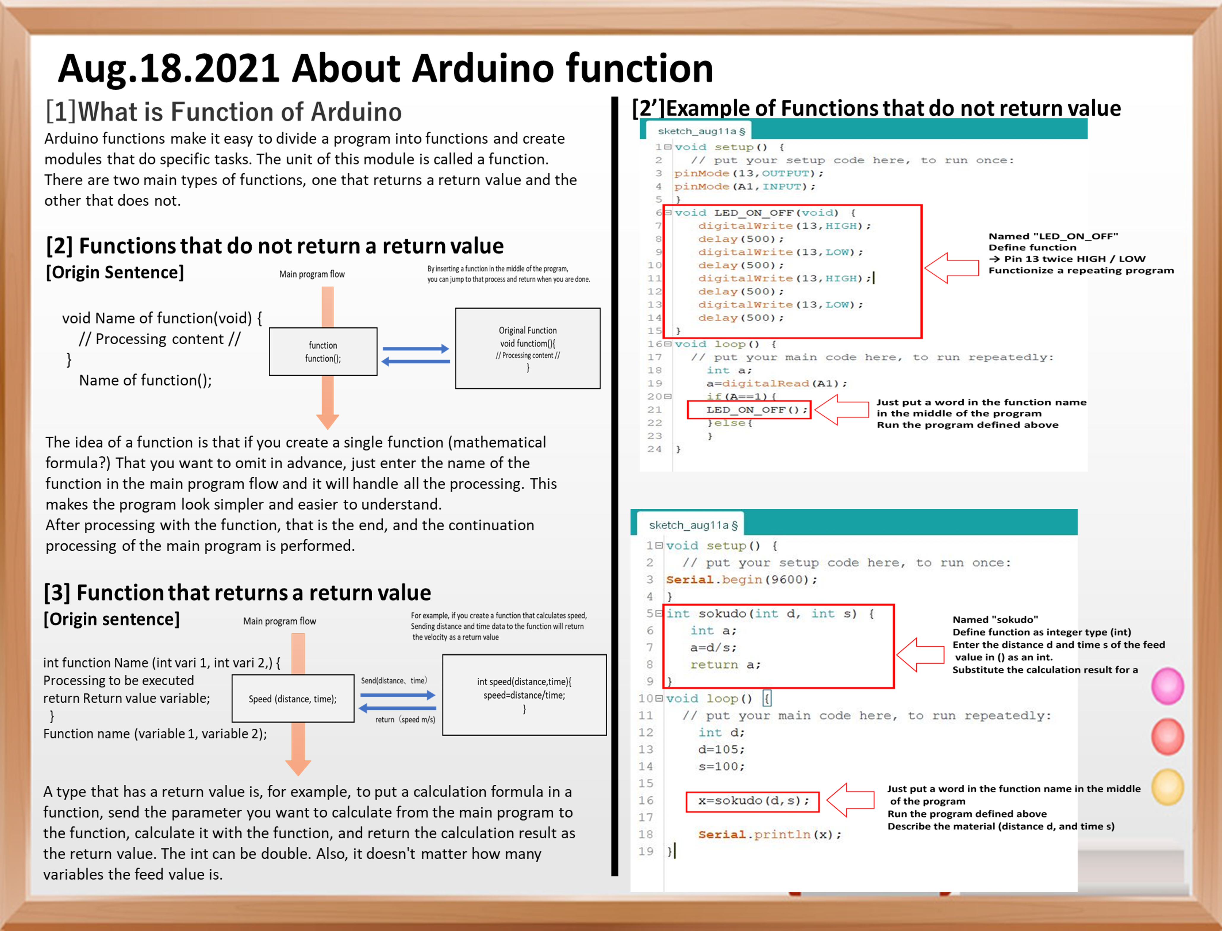
This time, I will talk about Arduino’s Void function.
Arduino functions make it easy to divide a program into functions and create modules that do specific tasks. The unit of this module is called a function.
There are two main types of
functions, one that returns a return value and the other that does not.
Functions that do not return a return value
First, the type of program that does not return a return value is shown below.
void name of function(void) {

  //Processing content//

}

      name of function();
A function that does not return a return value is used when you want the function to do only some work and the work result is not used in the sketch. In some cases, information is passed to a function (called an argument) to make it work.
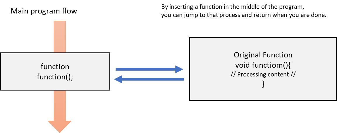
The idea of a function is that if you create a single function (mathematical formula?) That you want to omit in advance, just enter the name of the function in the main program flow and the process will go through. It does the job, making the program look simpler and easier to understand.
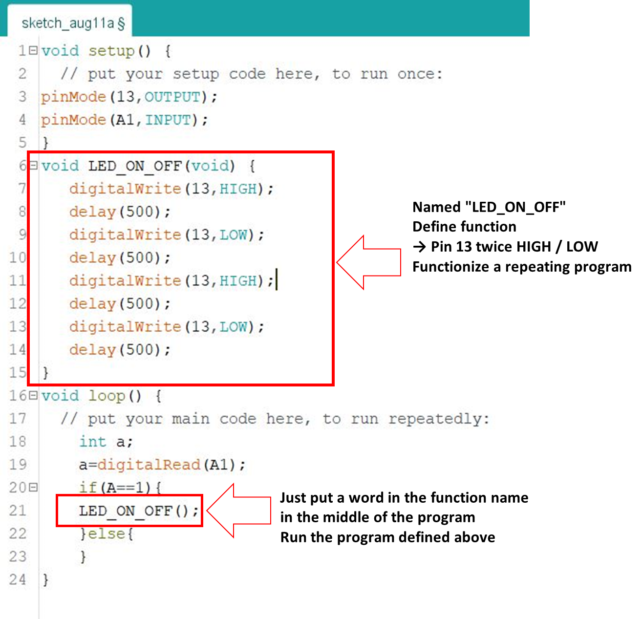
The figure below is an example of the program.
void setup() {
  // put your setup code here, to run once:
pinMode(13,OUTPUT);
pinMode(A1,INPUT);
}
void LED_ON_OFF(void) {
   digitalWrite(13,HIGH);
   delay(500);
   digitalWrite(13,LOW);
   delay(500);
   digitalWrite(13,HIGH);
   delay(500);
   digitalWrite(13,LOW);
   delay(500);
}
void loop() {
  // put your main code here, to run repeatedly:
    int a;
    a=digitalRead(A1);
    if(A==1){
    LED_ON_OFF();
    }else{
    }
}
A diagram summarizing this is shown below.
The program that turns the LED on / off with void LED_ON_OFF (void) {processing} is made into a function at the top, and the function can be executed just by saying the function name in the middle of the program.
Function that returns a return value
Next, it is a type of program that returns a return value.
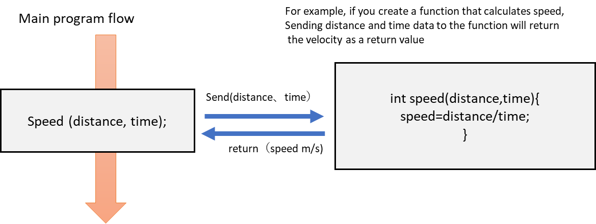
A type with a return value is, for example, to put a calculation formula in a function, send the parameter you want to calculate from the main program to the function, calculate it with the function, and return the calculation result as the return value.
In the example below, we want to make the velocity calculation a function.
Shows the definition of a program that returns a return value.
int function name (int variable 1, int variable 2, ...) {

      What to do

Return return value variable;
}

Function name (variable 1, variable 2 ...);
Note that int can be double. Also, it doesn’t matter how many variables the feed value is.
From the main program, send the distance and time parameters to the function. It is calculated in the function and the calculation result (speed) is returned as the return value.
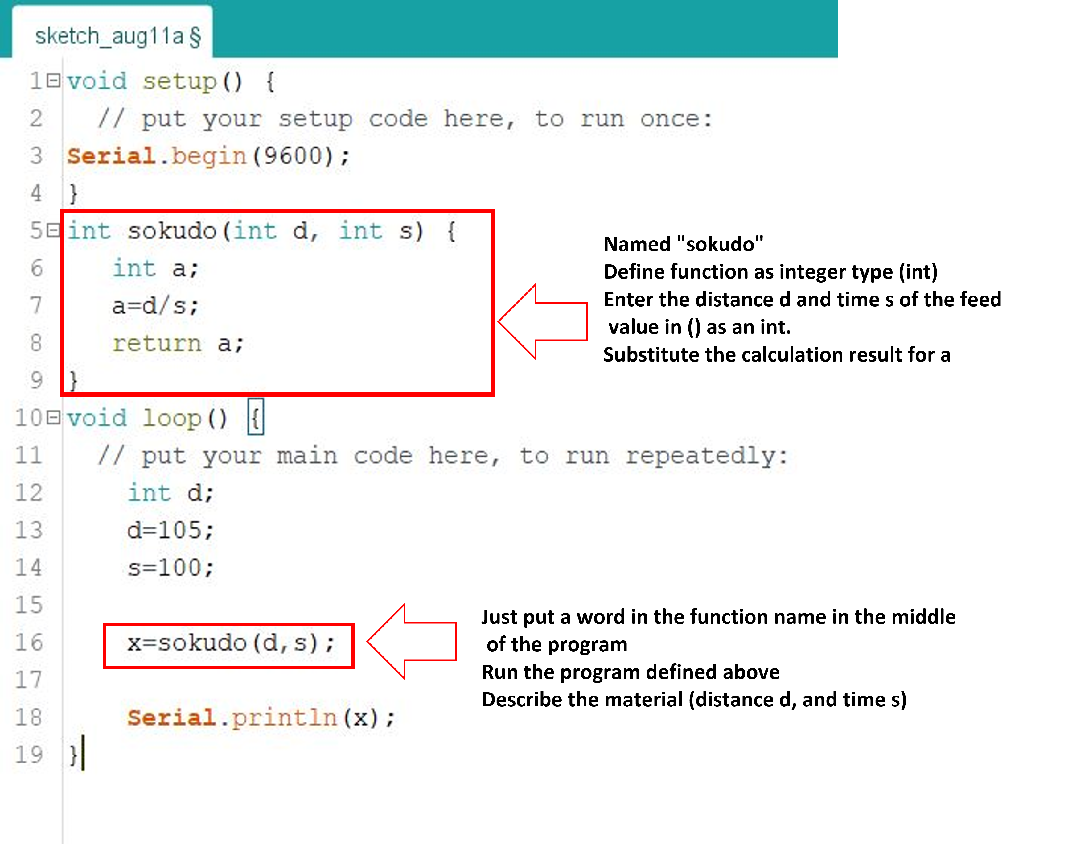
The following is an example program.
void setup() {
  // put your setup code here, to run once:
Serial.begin(9600);
}
int sokudo(int d, int s) {
   int a;
   a=d/s;
   return a;
}
void loop() {
  // put your main code here, to run repeatedly:
    int d;
    d=105;
    s=100;

    x=sokudo(d,s);

    Serial.println(x);
}
Define a function named sokudo as an integer type (int), describe the distance d and time s of the feed value in () as int, substitute the calculation result for a, and use return a; Returns as a return value.
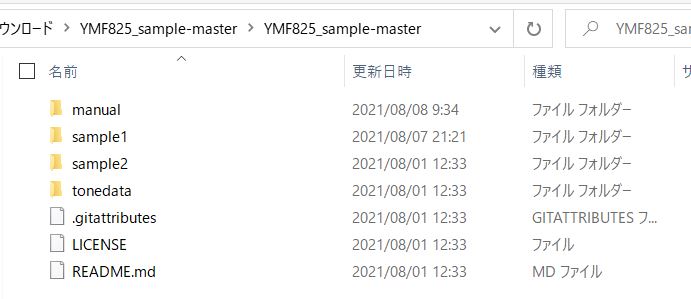
This is a continuation of the last time. This time, we will use the sample sketch of YMF-825 to make various sounds. Sample sketches were posted on GitHub. Please refer to the following. YMF-825 sample sketch Write this sample sketch to Arduino Nano.
When you open the folder on GitHub, you will find the following files.
The program of sample1 in this is used this time. The program ofsample1 is shown below.
To be honest, I didn’t understand it well, so I wrote it immediately.
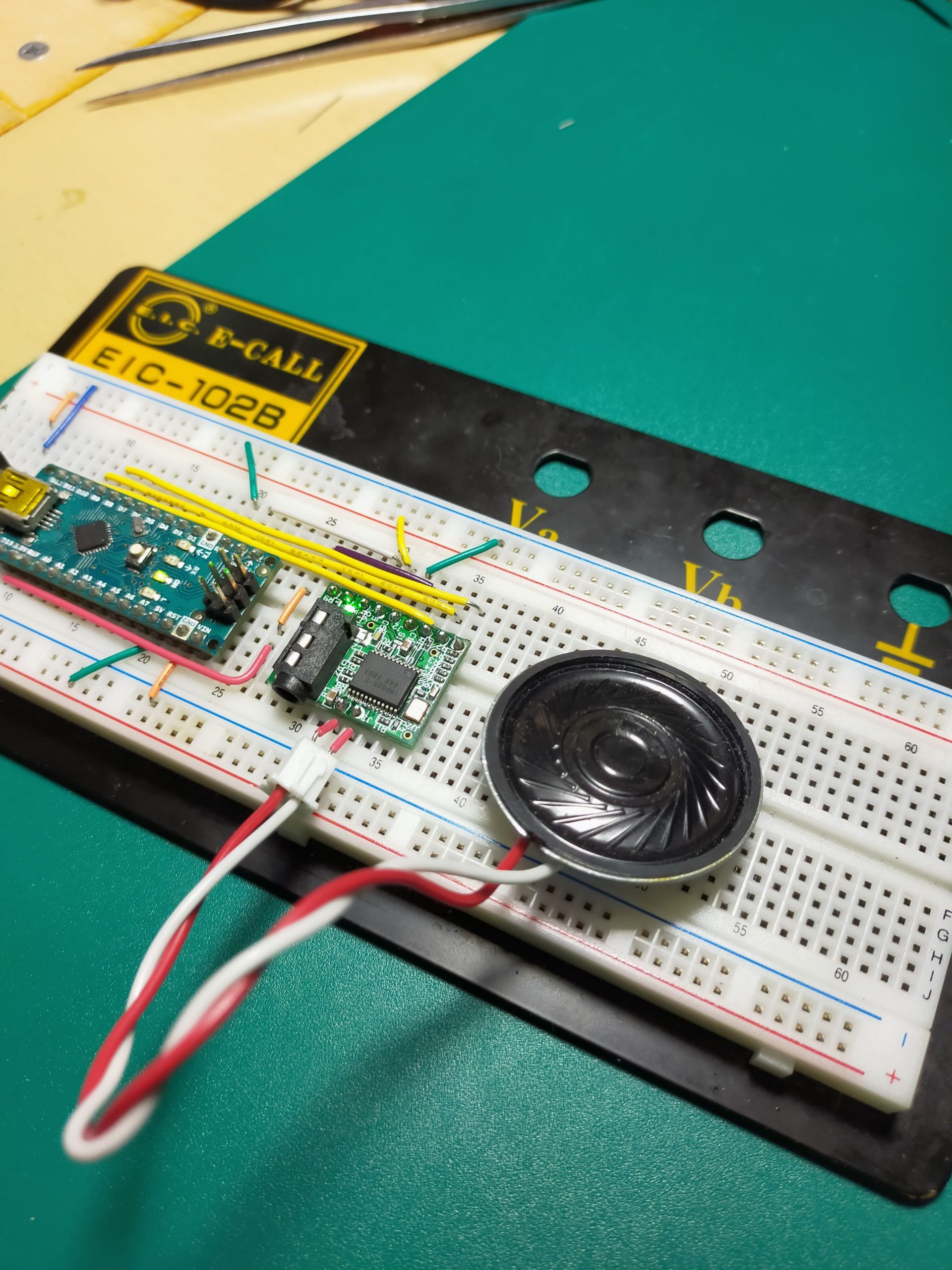
The speaker is directly connected to the SP of YMF-825.
The operation of is shown in the video below.
It seems that it repeats up to do, re, mi, fa, and so. Apparently, it seems that the scale is played by the processing in the void loop at the bottom of this program.
void loop() {
  // put your main code here, to run repeatedly:
  keyon(0x14,0x65);    //ド
  delay(500);
  keyoff();
  delay(200);
  keyon(0x1c,0x11);    //レ
  delay(500);
  keyoff();
  delay(200);
  keyon(0x1c,0x42);       //ミ
  delay(500);
  keyoff();
  delay(200);
  keyon(0x1c,0x5d);    //ファ
  delay(500);
  keyoff();
  delay(200);
  keyon(0x24,0x17);        //ソ
  delay(500);
  keyoff();
  delay(200);
}
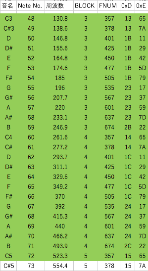
It seems that the hexadecimal number hour (0x14,0x65) in keyon determines the scale. However, the numbers are not continuous, and even if they are converted to decimal numbers, they do not seem to be frequencies. After a lot of research, I didn’t understand how it works, but Eguchi Kazuyuki’s Qiita blog showed the scale data to be written here. It seems that the data is not always accurate, so please refer to it at your own risk. About the scale parameters of YMF825 https://qiita.com/KazuyukiEguchi/items/8e7192a0114250f8898f
Since it is, it seems that you can use it if you refer to it from here for the scale. (Thank you very much)
Next is the tone. Depending on the settings, it seems that various sounds can be produced, and you can freely make pianos, guitars, etc. It is decided by the number of the array of tonedata [35] in void set_tone in the sample code.
There are eight types of sound sources here, GrandPiano E.Piano TenorSax PickBass TnklBell NewAgePd RimShot Castanets, and it seems that you can change the tone by copying and pasting them.
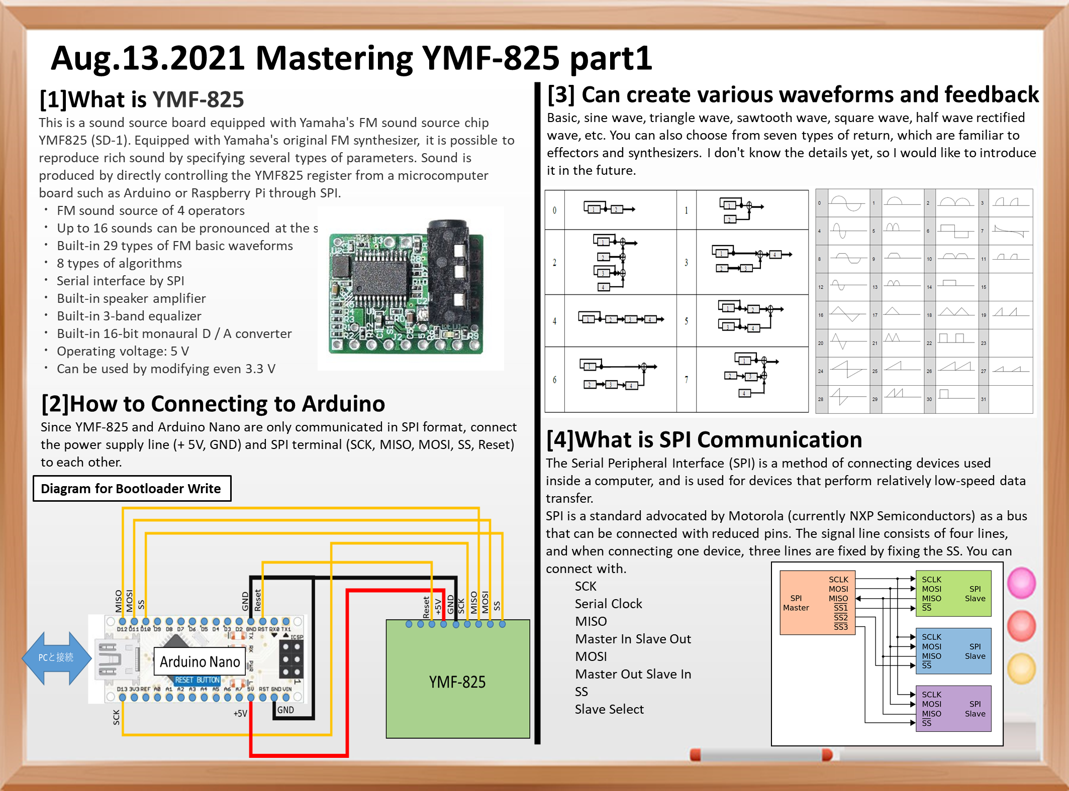
Sound is produced by directly controlling the YMF825 register from a microcomputer board such as Arduino or Raspberry Pi through SPI. Since it also has a speaker amplifier, there is no need to prepare an amplifier circuit separately.
* Although it is equipped with a 3.5 mm headphone jack, earphones that use 4-pole CTIA such as for iPhone cannot be used (OMTP ones can be used). ** From Switch science’s sales page **
Specifications
4 operator FM sound source
Up to 16 sounds can be produced at the same time
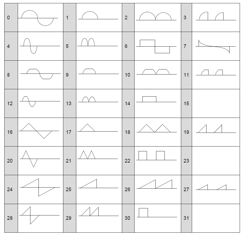
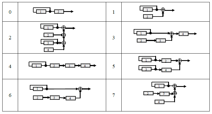
29 types of FM basic waveforms built-in, 8 types of algorithms
SPI Serial interface by
Built-in speaker amplifier
Built-in 3-band equalizer
Built-in 16-bit monaural D / A converter
Operating voltage: 5 V
3.3 V can also be used by modifying
** Image quote from Switch science **
A sample sketch is posted on GitHub, so I used it as a reference.
Basic, sine wave, triangle wave, sawtooth wave, square wave, half wave rectified wave, etc.
7 types of return can be applied
You can also choose from seven types of return, which are familiar to effectors and synthesizers.
I don’t know the details yet, so I would like to introduce it in the future.
What is SPI Communication
The Serial Peripheral Interface (SPI) is a method of connecting devices used inside a computer, and is used for devices that perform relatively low-speed data transfer.
SPI is a standard proposed by Motorola (currently NXP Semiconductors) as a pin-saving bus.
The signal line consists of 4 lines, and when connecting one device, it can be connected with 3 lines by fixing the SS.
SCK Serial Clock
MISO Master In Slave Out
MOSI Master Out Slave In
SS Slave Select
SPI communication connection (* quoted from Wikipedia)
Simple operation circuit example
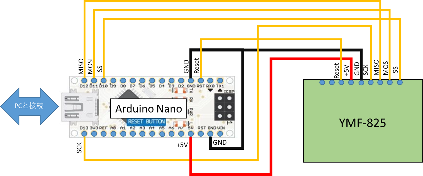
Next is the connection diagram.
Connection with YMF-825
Since YMF-825 and Arduino Nano are only communicated in SPI format, connect the power supply line (+ 5V, GND) and SPI terminal (SCK, MISO, MOSI, SS, Reset) to each other.
I wrote a bootloader for ATmega328 in my previous blog. This time, as a continuation of this, I will write a program on ATmega328 like Arduino. First of all, you need to connect to a PC to write the program. However, the ATmega328 does not have USB. Well, I think I will prepare a genuine Arduino again, but a cheaper one can be used instead. That is the USB-serial converter.
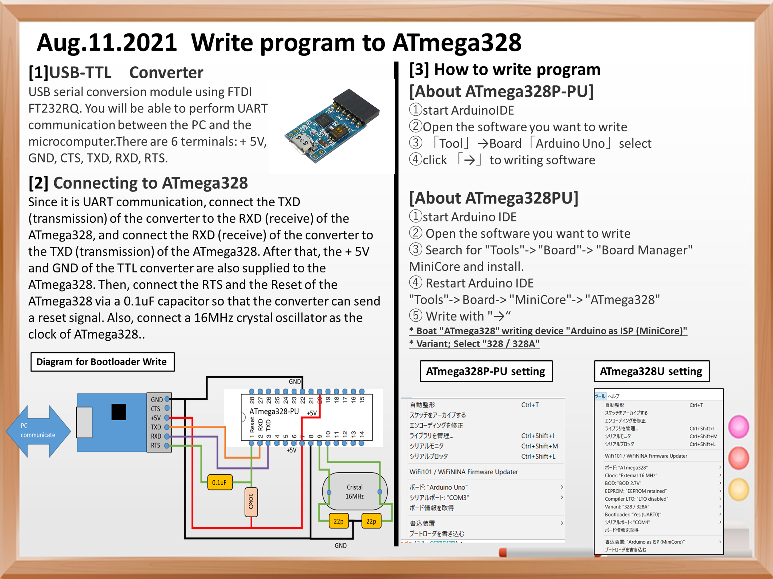
USB-TTL converter
USB serial conversion module using FTDI’s FT232RQ. -A wide range of drivers are available from Windows XP to 10. -The signal level of 5V / 3.3V can be changed with the DIP switch.
The terminals are + 5V, GND, CTS, TXD, RXD, and RTS. TXD, RXD means that it is UART communication.
Connect to ATmega328
Next is how to connect with ATmega328.
Since it is UART communication, connect the TXD (transmission) of the converter to the RXD (receive) of the ATmega328, and connect the RXD (receive) of the converter to the TXD (transmission) of the ATmega328. After that, the + 5V and GND of the TTL converter are also supplied to the ATmega328. Then, connect the Reset of RTS and ATmega328 via a 0.1uF capacitor so that the converter can send a reset signal. After that, connect a 16MHz crystal oscillator as the clock of ATmega328.
Arduino IDE settings
If you connect the TTL converter to USB, you can write like a normal Arduino. However, you can write only to the microcomputer whose boot loader has already been written. Please refer to the following for how to write the boot loader. -Boot loader writing method
Well, although I said that I can write like Arduino, even with ATmega328, the settings are slightly different between ATmega328P-PU and ATmega328U.
ATmega328P-PU write settings
The ATmega328P-PU is a little expensive, but it uses the same chip as the genuine Arduino UNO, so on the setting screen that opens “Tools”, select the board “Arduino Uno” and connect the TTL converter. If you select the COM port you have, you can write to it.
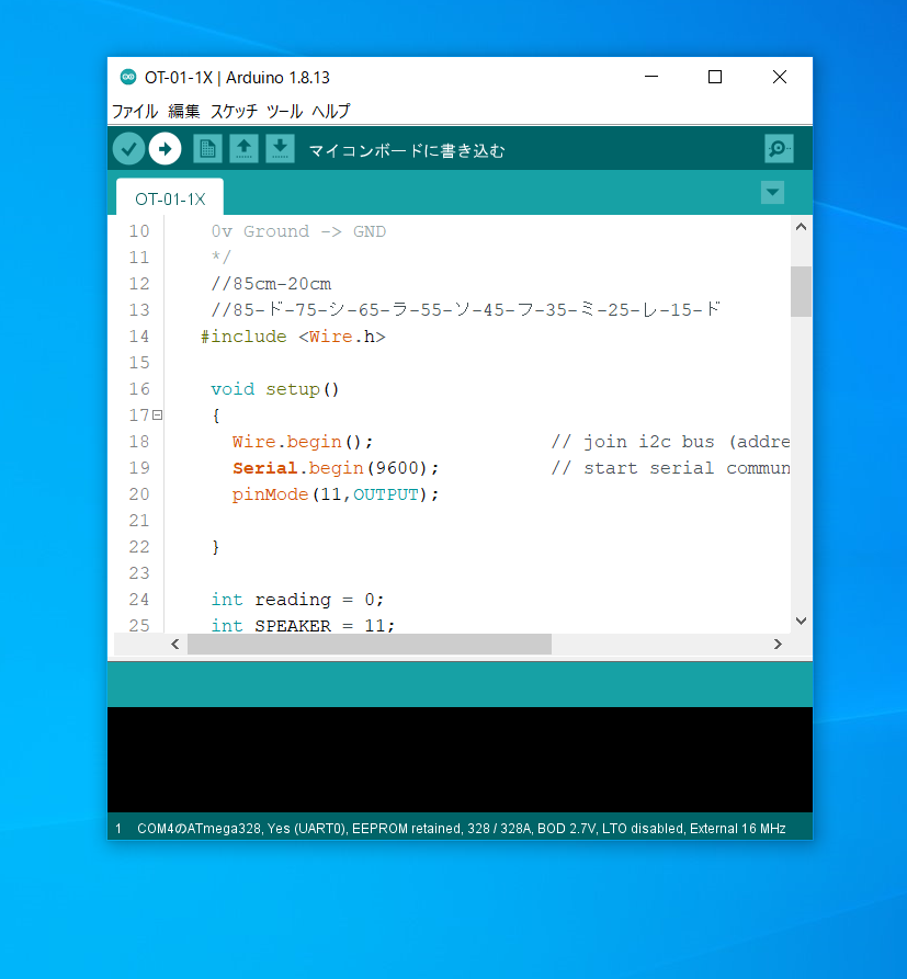
Open Arduino IDE and program
ATmega328P-PU settings
ATmega328 U(ATmega328PU)
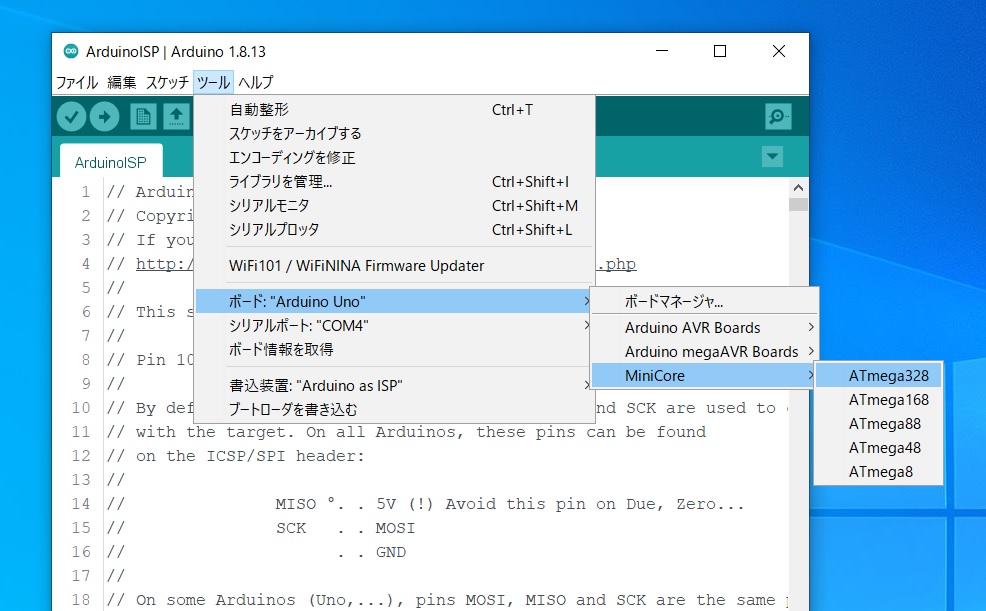
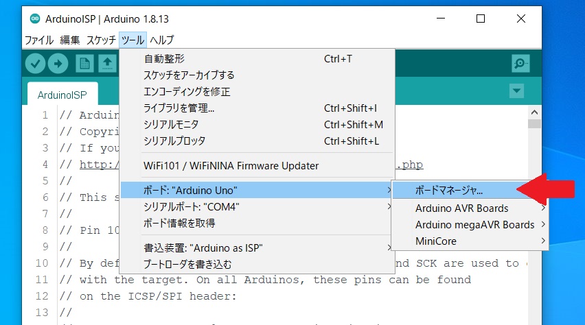
ATmega328 cannot be written by the board manager that is included in Arduino from the beginning. Open “Tools”-> “Board”-> “Board Manager”, search for MiniCore, and install.
Launch Board Manager
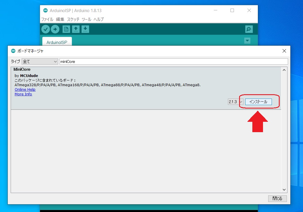
Install MiniCore
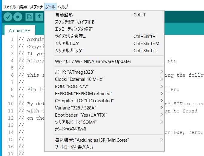
Restart Arduino and select “Tools”-> Board-> “MiniCore”-> “ATmega328”.
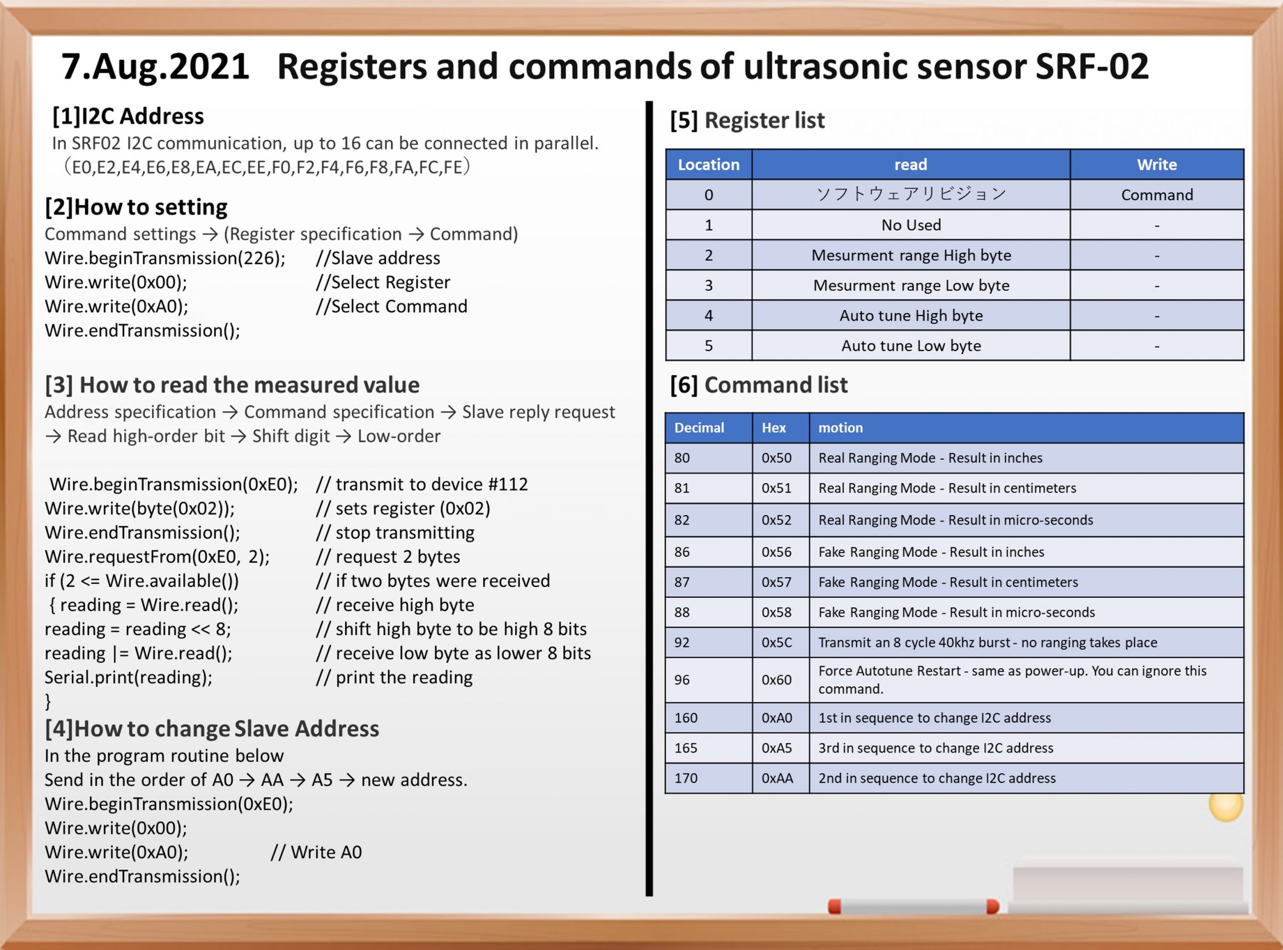
This time, I investigated the command of the ultrasonic sensor SRF-02. First , there are two modes of communication of SRF-02, I2C and UART, Now I focus on I2C.
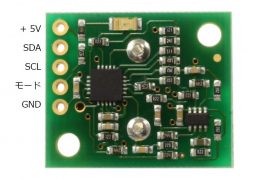
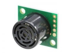
the main features of SRF-02.
◆ Main specifications ・ Microcomputer : 16F687-I / ML ・ Measurement range: 16cm ~ 6m ・ Power supply: 5V (current consumption 4mA Typ.) ・ Frequency used: 40KHz. – Analog gain: 64 levels of automatic gain control -Connection mode: Mode 1 = I2C, Mode 2 = Serial bus ・ Fully automatic adjustment function: No calibration required after turning on the power ・ Distance measurement timing: Echo time measurement, task control by host ・Unit of measurement: μS (microseconds), millimeters, inches ・ Size: 24mmx20mmx17mm ・ Input / output terminal: 5 pins ・ Weight: 4.6 grams
Main commands of SRF-02
Next are the main commands used by SRF-02. The communication method of the command uses the Arduino Wire library for communication. For details, see Previous blog.
Communication method with I2C
To use F02 in I2C mode, open the mode pin.
For I2C communication, up to 16 can be connected in parallel. Since they are connected in parallel, addresses are assigned to each Slave (ultrasonic sensor). The factory address for SRF02 is 0xE0. The address can be changed by the user, and up to 16 addresses (E0, E2, E4, E6, E8, EA, EC, EE, F0, F2, F4, F6, F8, FA, FC, FE) are used. can.
register
The SRF-02 has 6 types of registers.
Location
Read
Write
0
Software rivision
Command Register
1
No Used
–
2
Sense Range High byte
–
3
Sense Range Low byte
–
4
smallest Auto tune-High byte
–
5
smallest Auto tune Low byte
–
Register
Of the 6 registers, only register 0 can be written from Master.
Various settings of SRF-02 can be made by putting a numerical value in the 0th register.
When reading from 0, the software revision is returned. The first is an unused pin.
The 2nd and 3rd registers are the registers that return the measured values. The measured value is returned with a maximum capacity of 2 bytes. Since one register is 1 byte, two registers (2,3) are required. This measurement is returned in inches, centimeters, microseconds, etc., depending on the settings.
In other words, if you specify 0 at the beginning, then you can refer to the measured value in the 2nd and 3rd registers.
Command of SRF-02
The following is the command specified for SRF-02 No. 0.
Decimal
Hex
motion
80
0x50
Real Ranging Mode – Result in inches
81
0x51
Real Ranging Mode – Result in centimeters
82
0x52
Real Ranging Mode – Result in micro-seconds
86
0x56
Fake Ranging Mode – Result in inches
87
0x57
Fake Ranging Mode – Result in centimeters
88
0x58
Fake Ranging Mode – Result in micro-seconds
92
0x5C
Transmit an 8 cycle 40khz burst – no ranging takes place
96
0x60
Force Autotune Restart – same as power-up. You can ignore this command.
160
0xA0
1st in sequence to change I2C address
165
0xA5
3rd in sequence to change I2C address
170
0xAA
2nd in sequence to change I2C address
list of Command
If necessary, write the above command to the first command register, wait for the required time, and read the result. The echo buffer is cleared at the beginning of each range. The range lasts up to 66msec. After this, the measured value is read from the 2nd and 3rd registers.
How to Command to SRF-02
What should I do when instructing SRF-02 from Master? The following is a program to set the measured value to cm for reference.
First, specify the Slave address (226) with Wire.beginTransmission (226) ;. The next thing to send is the register to connect. If you want to make any settings, Send 0 with Wire.write (0x00); to access register 0. Next, what you send is the command to set. For example, if you want to set the measured value to be returned in cm, you can send the command 0x51. Wire.write (0x51); This completes the settings, so Wire.endTransmission (); ends this communication. Although it depends on the content of the command, the basic flow is to specify a register → send the command for that register.
Program to read the measured value of SRF-02
Next is the method of reading the measured value from SRF-02.
      Wire.beginTransmission(0xE0); // transmit to device #112
      Wire.write(byte(0x02));      // sets register pointer to echo #1 register (0x02)
      Wire.endTransmission();      // stop transmitting


      Wire.requestFrom(0xE0, 2);    // request 2 bytes from slave device #112

      if (2 <= Wire.available())   // if two bytes were received
      {
        reading = Wire.read();  // receive high byte (overwrites previous reading)
        reading = reading << 8;    // shift high byte to be high 8 bits
        reading |= Wire.read(); // receive low byte as lower 8 bits
        Serial.print(reading);   // print the reading
        Serial.println("cm");
      }
First, when reading a numerical value from SRF-02, access the second register 0x02. That is the program up to the third line.
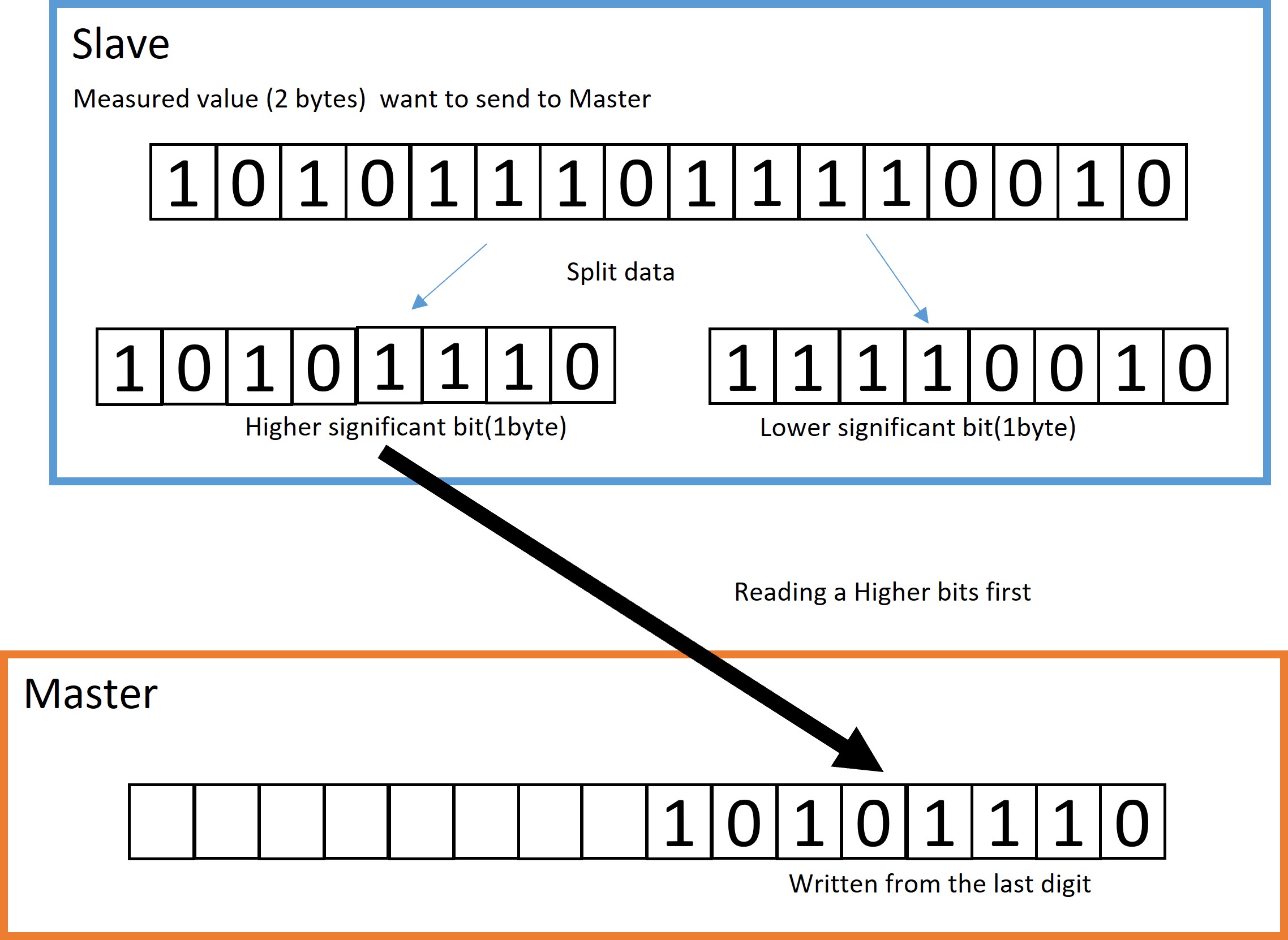
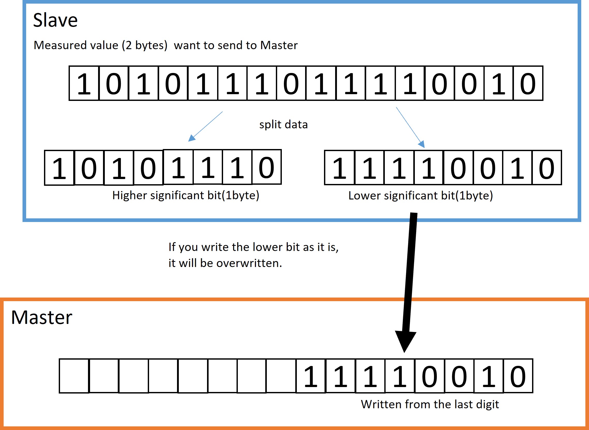
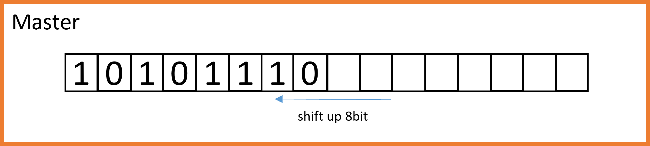
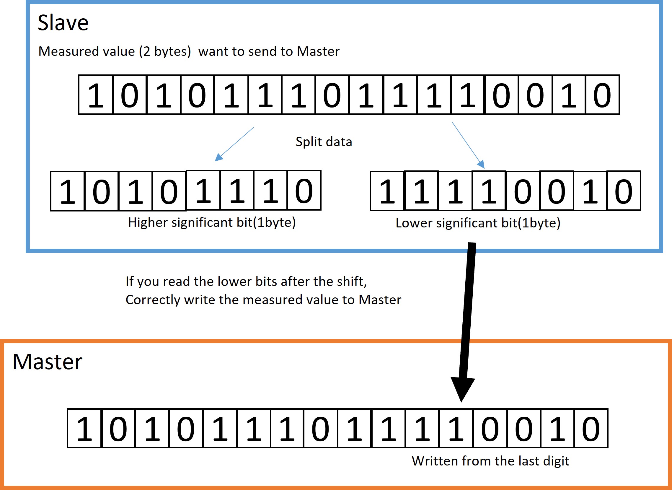
Next, prepare to receive data from SRF-02. That is Wire.requestFrom (0xE0, 2) ;. This means that it will receive 2 bytes of data from Slave at address E0. After that, you can receive the data with Wire.read () ;. However, since it has 2 bytes, the lower bits will be overwritten if it is received as it is. Therefore, first receive the data of the upper 8 bits (reading = Wire.read ();), shift the reading bit to (reading = reading & lt; & lt; 8;) 8 bits higher, and then skip to the next. The incoming number (lower bit) is received by (reading = Wire.read ();).
The data divided by Slave is written from the high-order bit.
If you write the lower bit as it is, it will be overwritten.
Therefore, the first written high-order bit is shifted up to 8 bits.
After that, if you write the lower bits, everything can be sent correctly.
How to SRF-02 addressing
Next is the SRF-02 addressing procedure. The method is simple, send the above commands 0xA0, 0xAA, 0xA5, in order, and finally send a new address to enter the mode to specify the address. For example, if you want to return from the original address E0 to the new address F4, run the following program. It’s very simple, isn’t it?
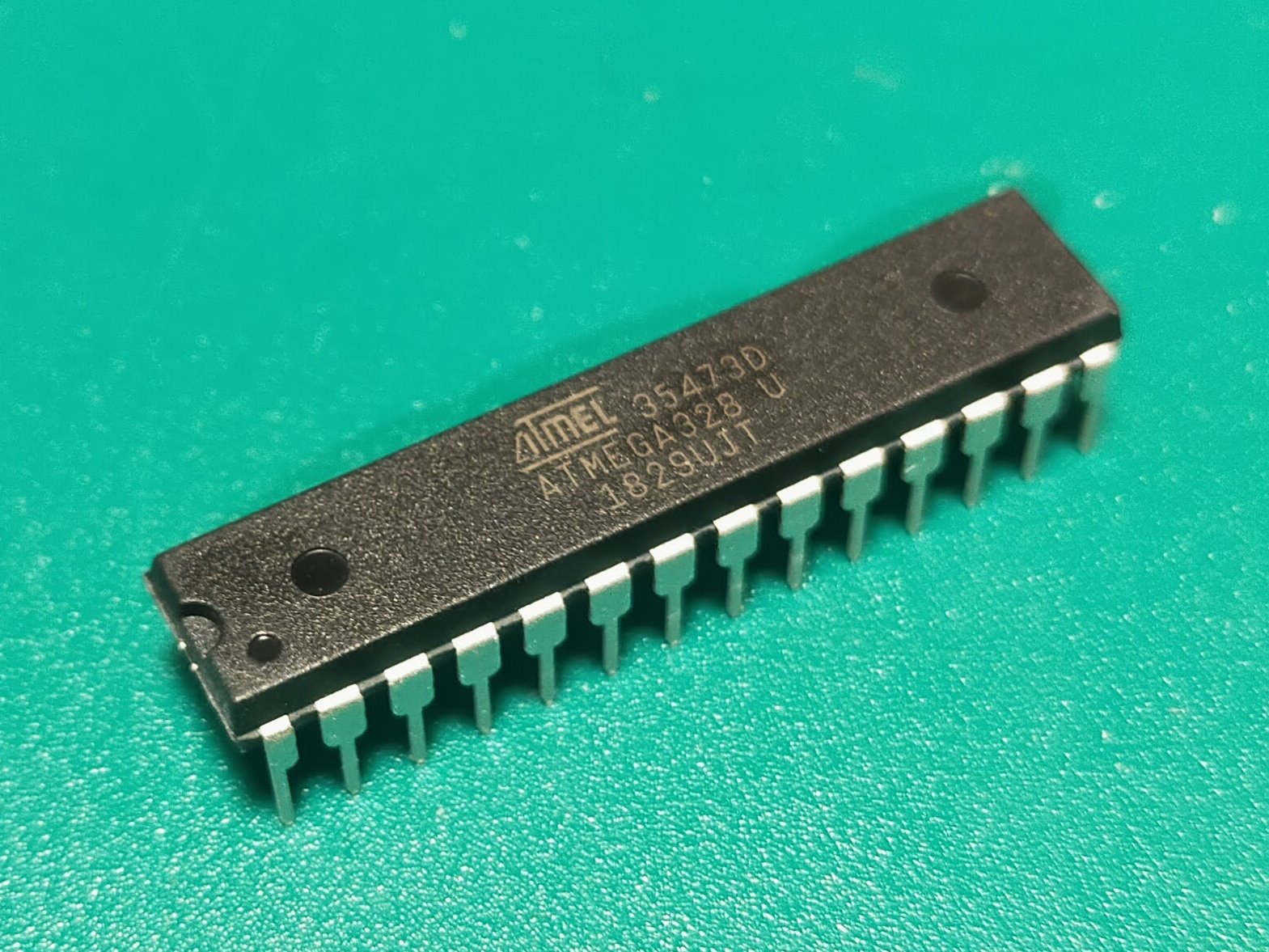
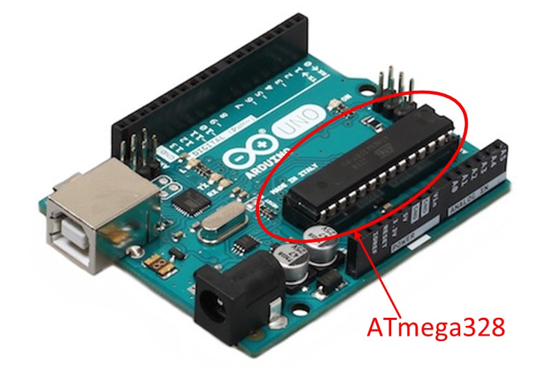
This time, we will process to use the commercially available AVR microcomputer ATmega328 as an Arduino. ATmega328 is a microcomputer chip installed in Arduino.
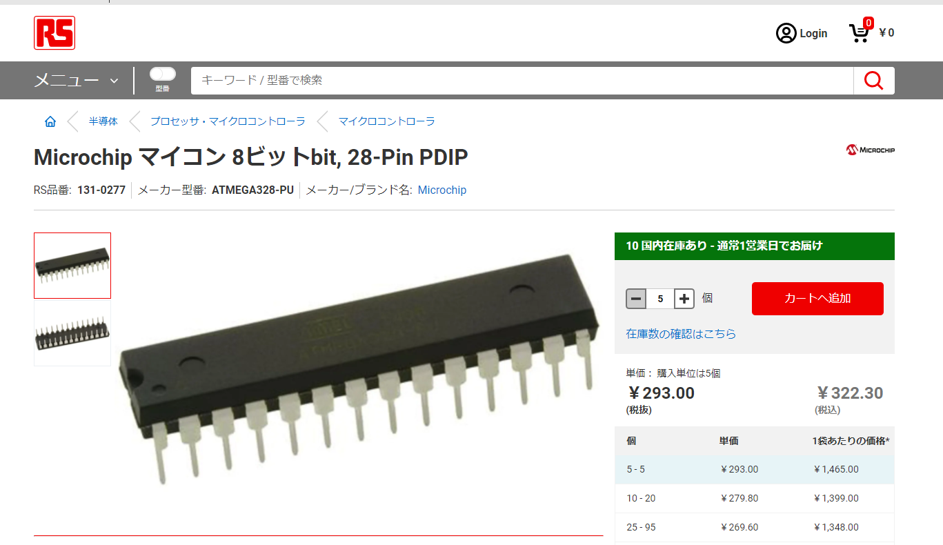
Arduino is about 3000 yen when you buy it at a fixed price. Since the board is also large, it is not suitable for mounting. Therefore, I will use ATmega328 as an Arduino by itself. ATmega328 can be purchased online. However, recently, due to the shortage of semiconductors, it is difficult to obtain surface mounts for ATmega328 and ATmega328P-PU. For now, it looks like it’s still in stock. RS Components costs 323 yen each. In other words, you can use a small size Arduino at 1/10 the price of Arduino.
This time, write a boot loader to use as Arduino in this IC.
What is a boot loader?
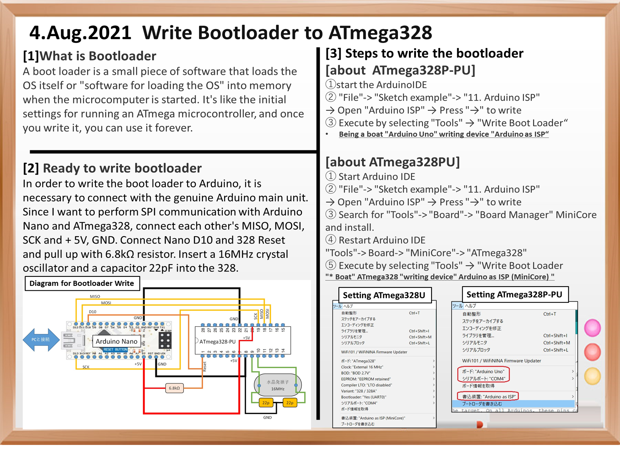
What is a boot loader
Boot is a slang term that means booting basic software such as an OS on a computer. The boot loader is a small piece of software that loads the OS itself or “software for loading the OS” into memory at this time. This program is the basic software for running ATmega microcontrollers. It’s like an initial setting, so once you write it, you can use it forever, and you can rewrite the software many times.
Ready to write bootloader
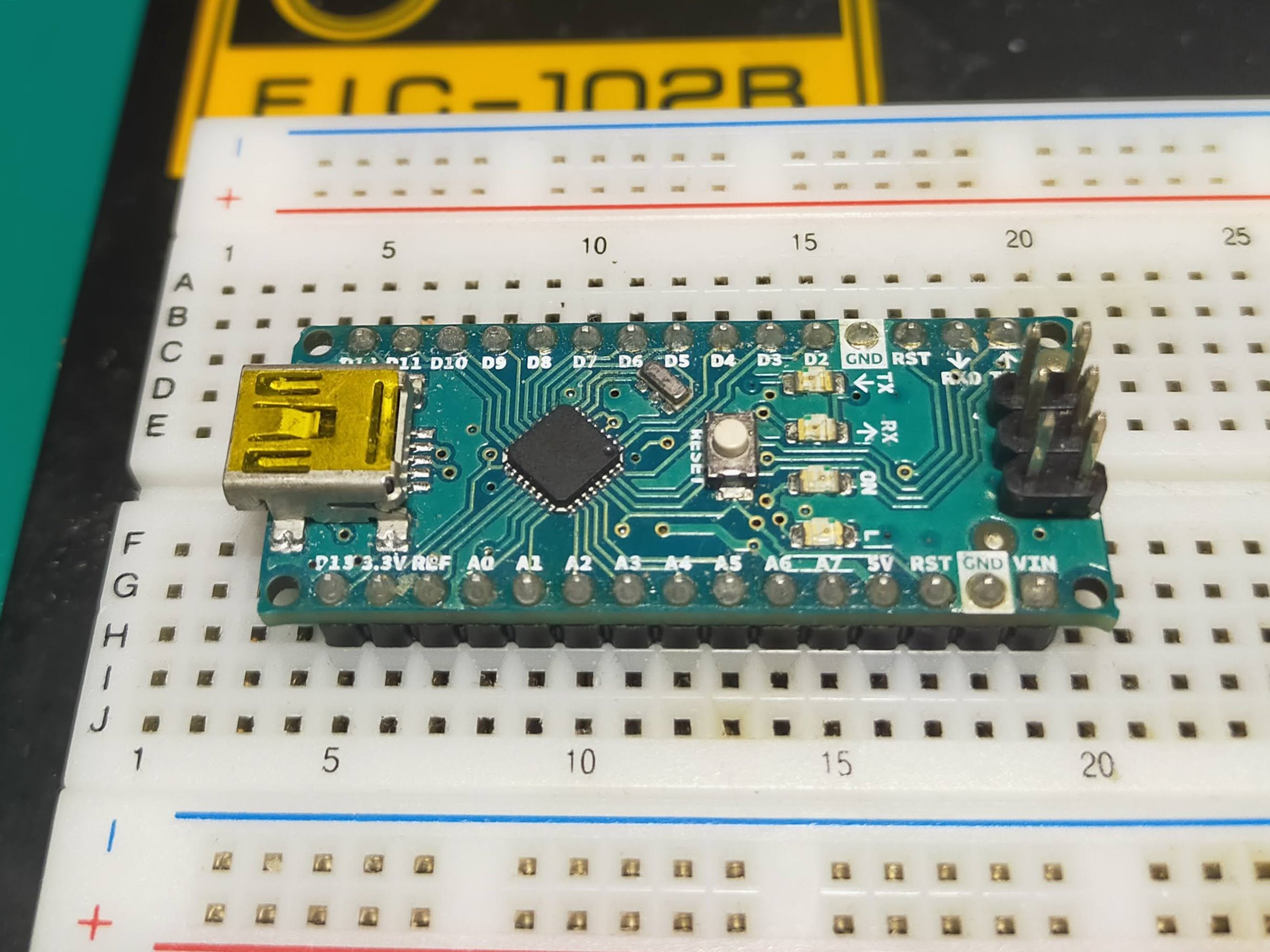
Please prepare a genuine Arduino to write the boot loader. It needs to communicate with ATmega328 by SPI method, which requires a genuine Arduino. The genuine Arduino can be basically anything. I used an Arduino Nano that can be stabbed on a breadboard.
Arduino Nano
ATmega328PU
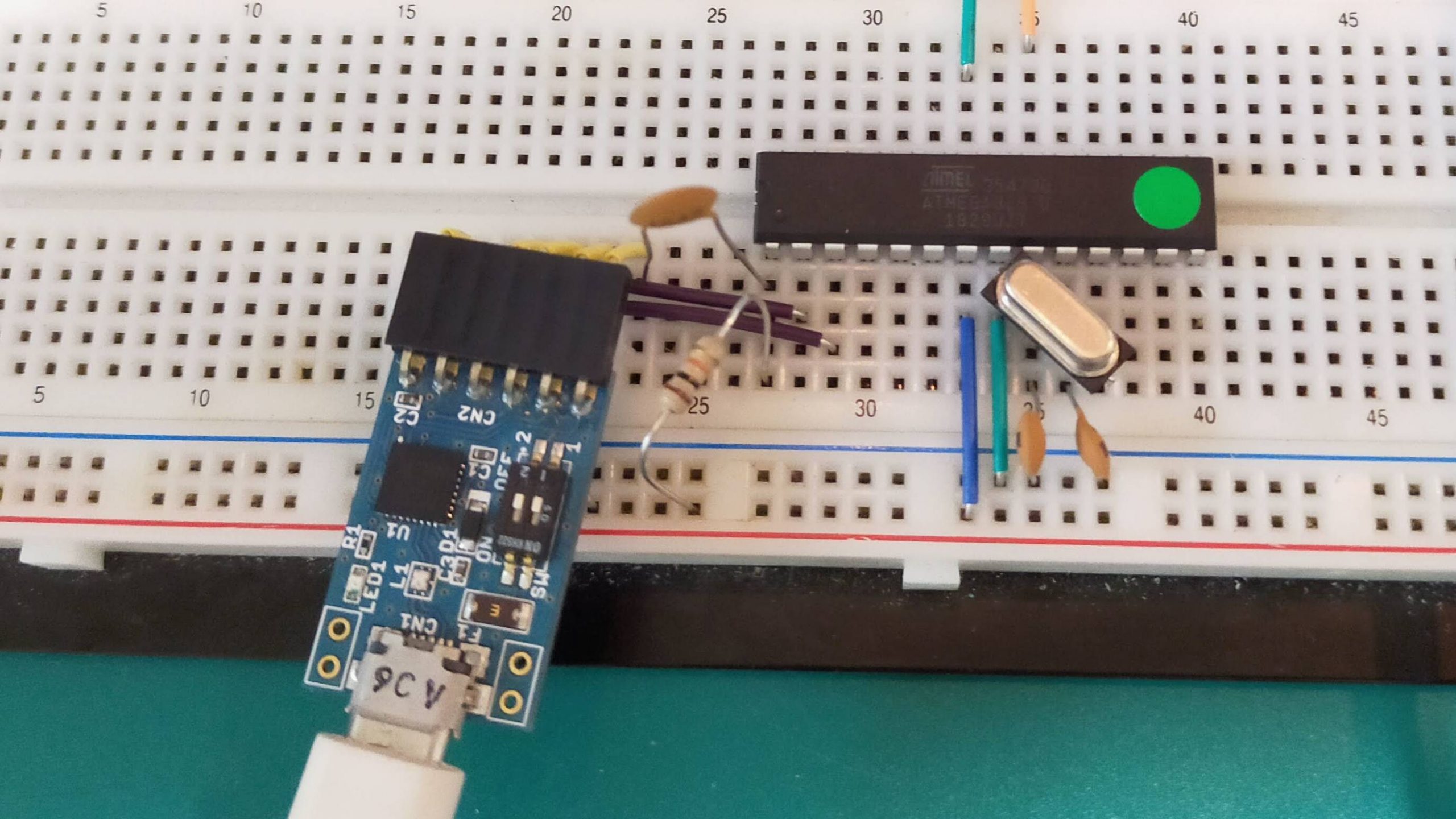
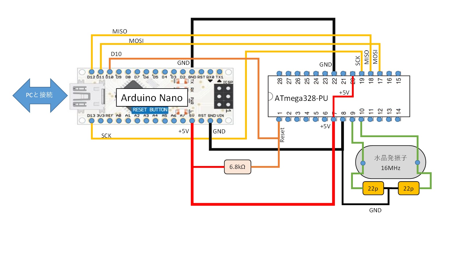
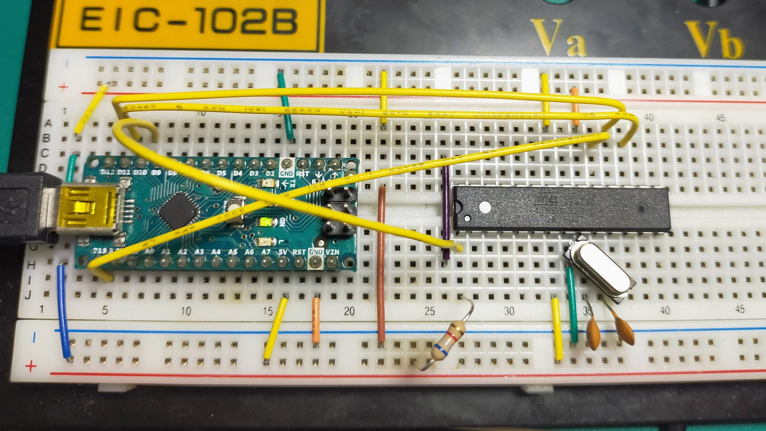
The wiring diagram of Arduino Nano and ATmega328PU is as shown below.
In short, I want to do SPI communication with Arduino Nano and ATmega328. Connect each other’s MISO, MOSI, SCK and + 5V, GND. After that, in order to reset ATmega328 at the timing specified by Arduino Nano, connect the Reset pin of Nano D10 and ATmega328 and pull up with a resistor of 6.8kΩ. After that, ATmega328 does not work without a clock, so I put a 16MHz crystal oscillator and a standard capacitor 22pF.
diagram of Bootloader Writing
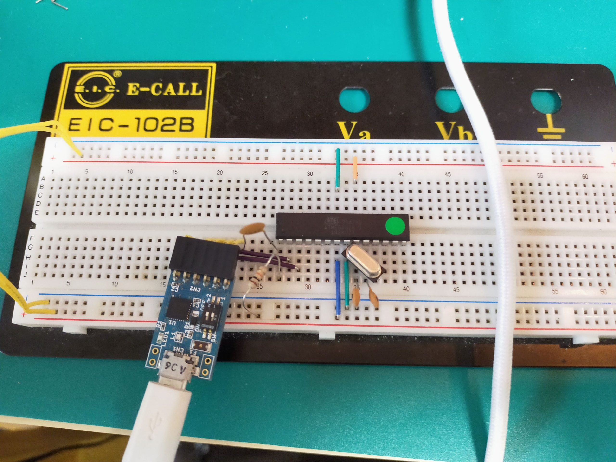
I actually wired it on a breadboard.
wired on a breadboard.
Arduino IDE settings
Next, set the Arduino writing software. First, the boot loader writing method is different between the ATmega328P-PU and ATmega328PU (part notation; ATMEGA328U) ICs to write. This is because the ATmega328PU, which was released as a low-priced version after ATmel changed to MicroChip, has a different writing variant.
Write the ATmega328P-PU bootloader
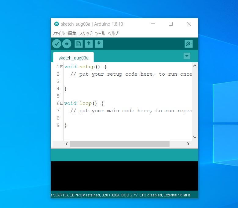
First, start the Arduino IDE. Please install the Arduino software from the link below.
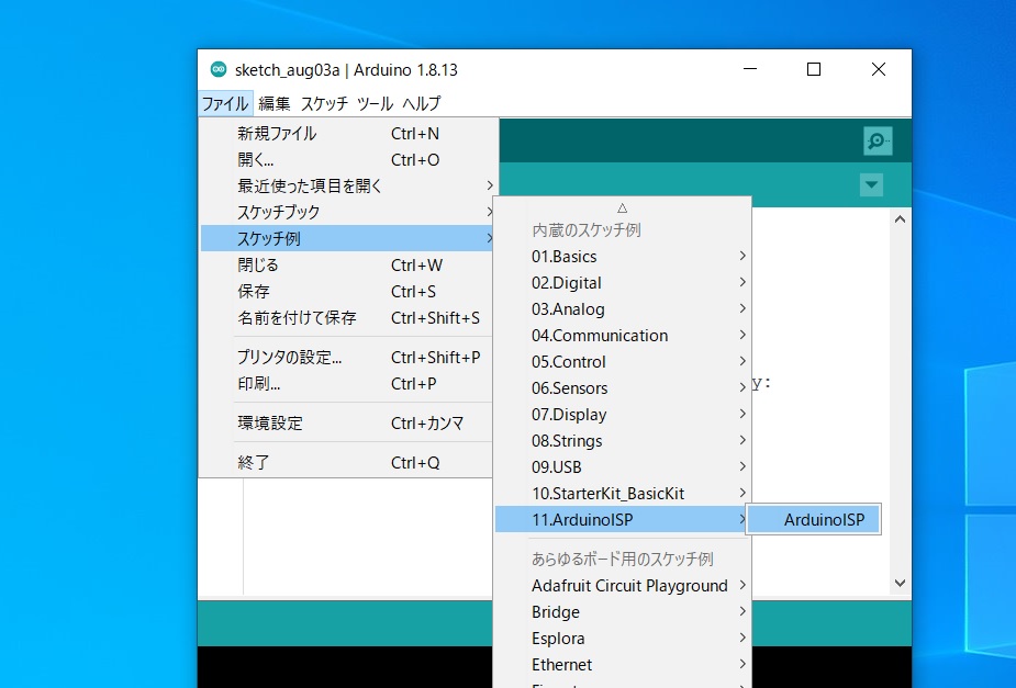
When the Arduino IDE starts, open “File”-> “Sketch example”-> “11. Arduino ISP”-> “Arduino ISP”.
Arduino IDEを起動
Arduino ISPを起動
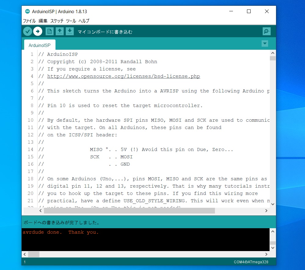
First, write the Arduino ISP software to the Arduino Nano. Now you can use the Arduino Nano as a writer.
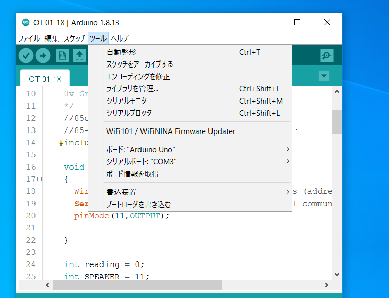
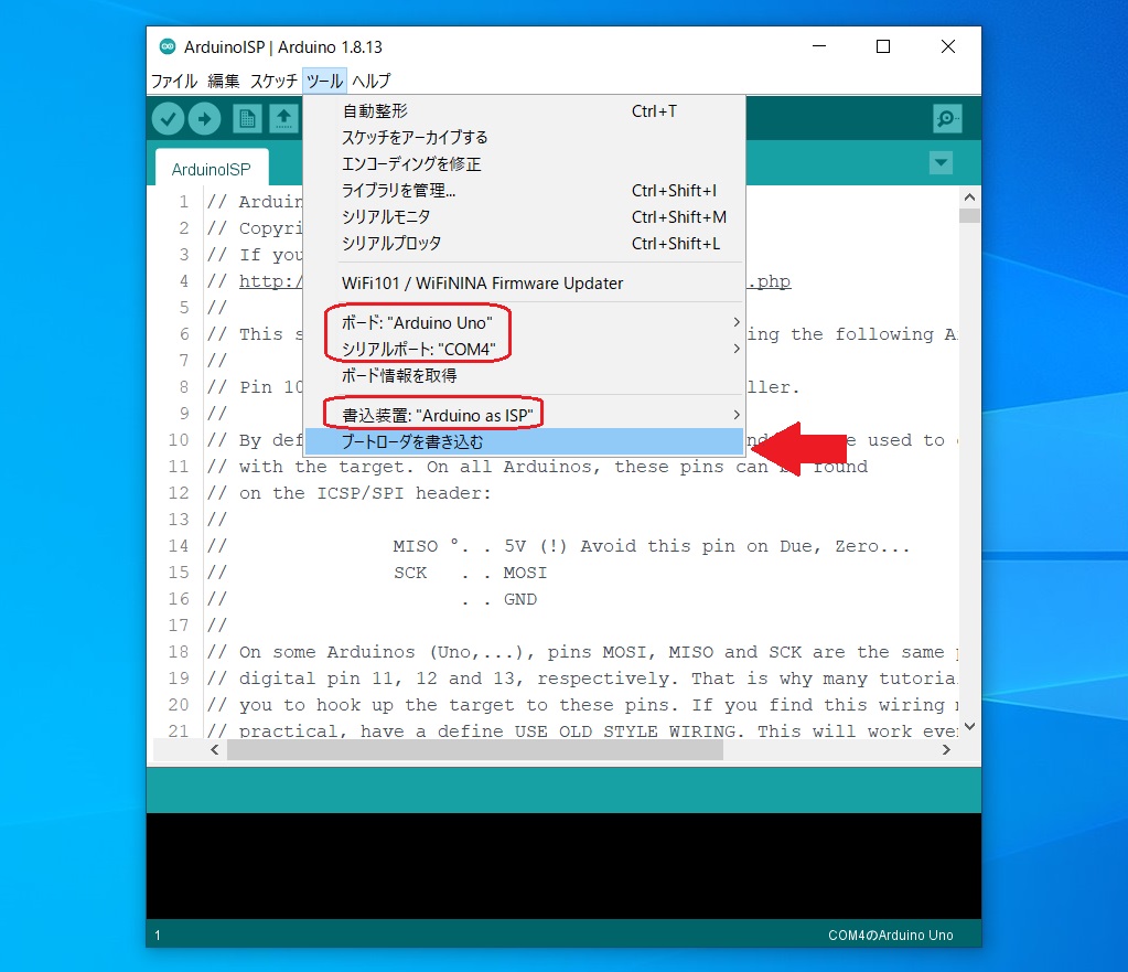
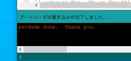
After that, press “Tools”, select the port “Arduino Uno”, the serial port “COM port connecting Arduino Nano”, the writing device “Arduino as ISP”, and select “Write boot loader” at the bottom. You can write the bootloader by pressing.
ArduinoNanoにArduinoISPのソフトを書き込む
ブートローダを書き込む
Write bootloader to ATmega328PU
The above is the same up to writing the ISP software from Arduino ISP to Arduino Nano.
ATmega328 cannot be written by the board manager that is included in Arduino from the beginning.
Open “Tools”-> “Board”-> “Board Manager”, search for MiniCore, and install.
ボードマネージャーを起動
MiniCoreをインストール
Restart Arduino and select “Tools”-> Board-> “MiniCore”-> “ATmega328”.
This time, I2C communication with an ultrasonic sensor to Arduino.
Among them, the Wire function is especially convenient.
First, I will give an overview of I2C communication.
Todays Topics
What is I2C communication?
I2C (Inter-Integrated Circuit) is a method of serial communication with peripheral devices advocated by Philips, and is a method that mainly realizes high-speed communication with EEPROM memory ICs.
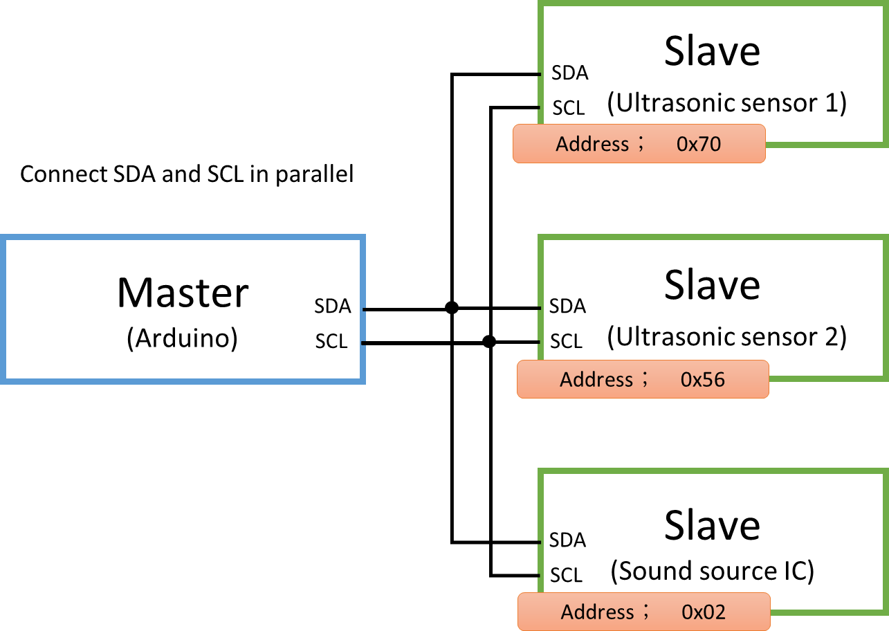
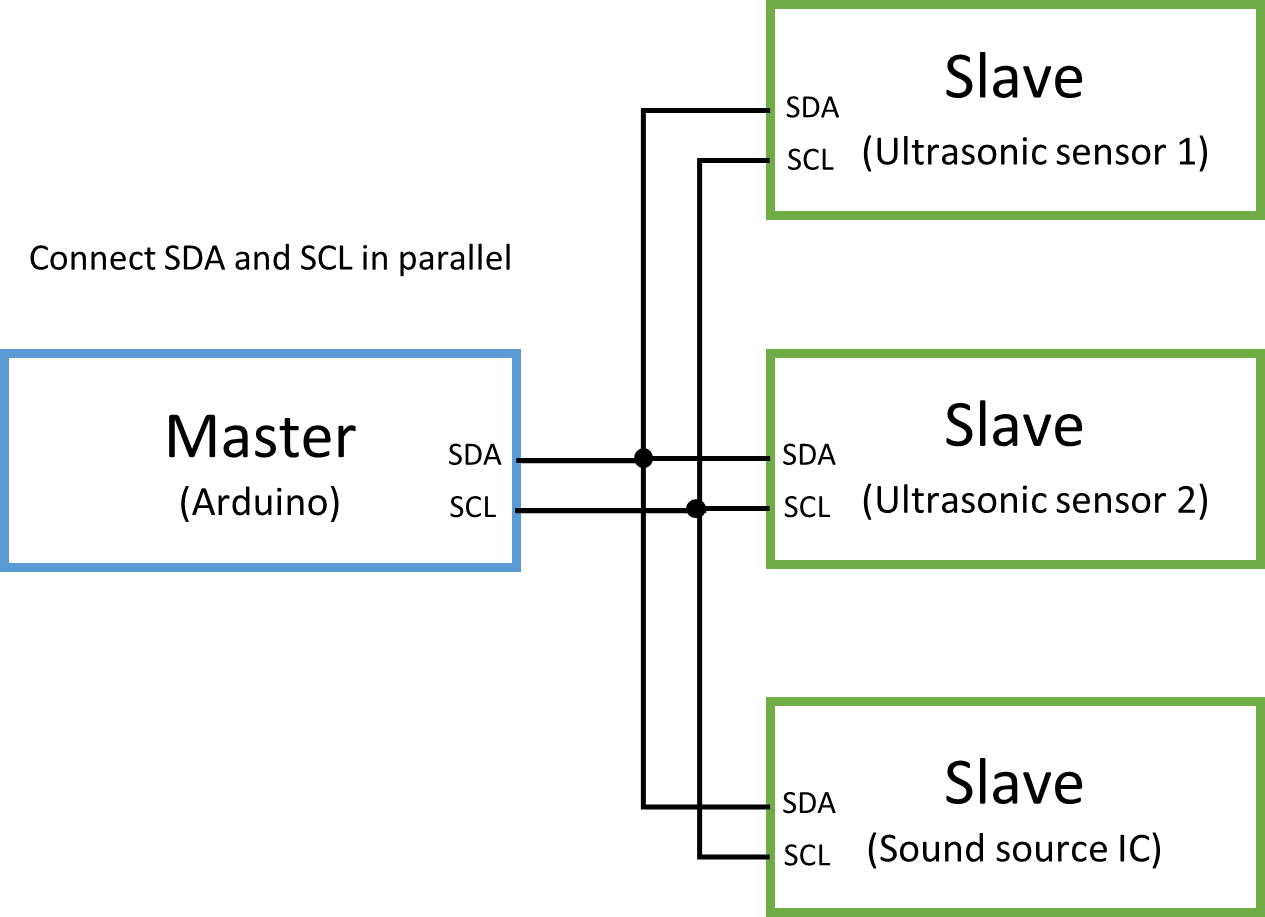
In the basic configuration, the master side and the slave side are clearly separated, and the master side has the initiative of all controls. Only one master can be connected, but many slaves can be connected.
I2C Network
I2C connects all the same lines (SDA, SCL) in parallel. Even though they are in parallel, they can communicate with each other because they are assigned addresses, just like Internet networks.
The address can be binary, hexadecimal, or decimal. For example, when writing in hexadecimal, write in the form of 0x70 or 0x56. Also, the master has no address.
When communicating, be sure to first declare the Slave destination (address) before sending the data. Even when the destination changes, the destination is said one by one.
Even in human life, you always write the address in letters and courier services. It’s the same. Speaking of course, it’s natural.
An address is assigned to each Slave
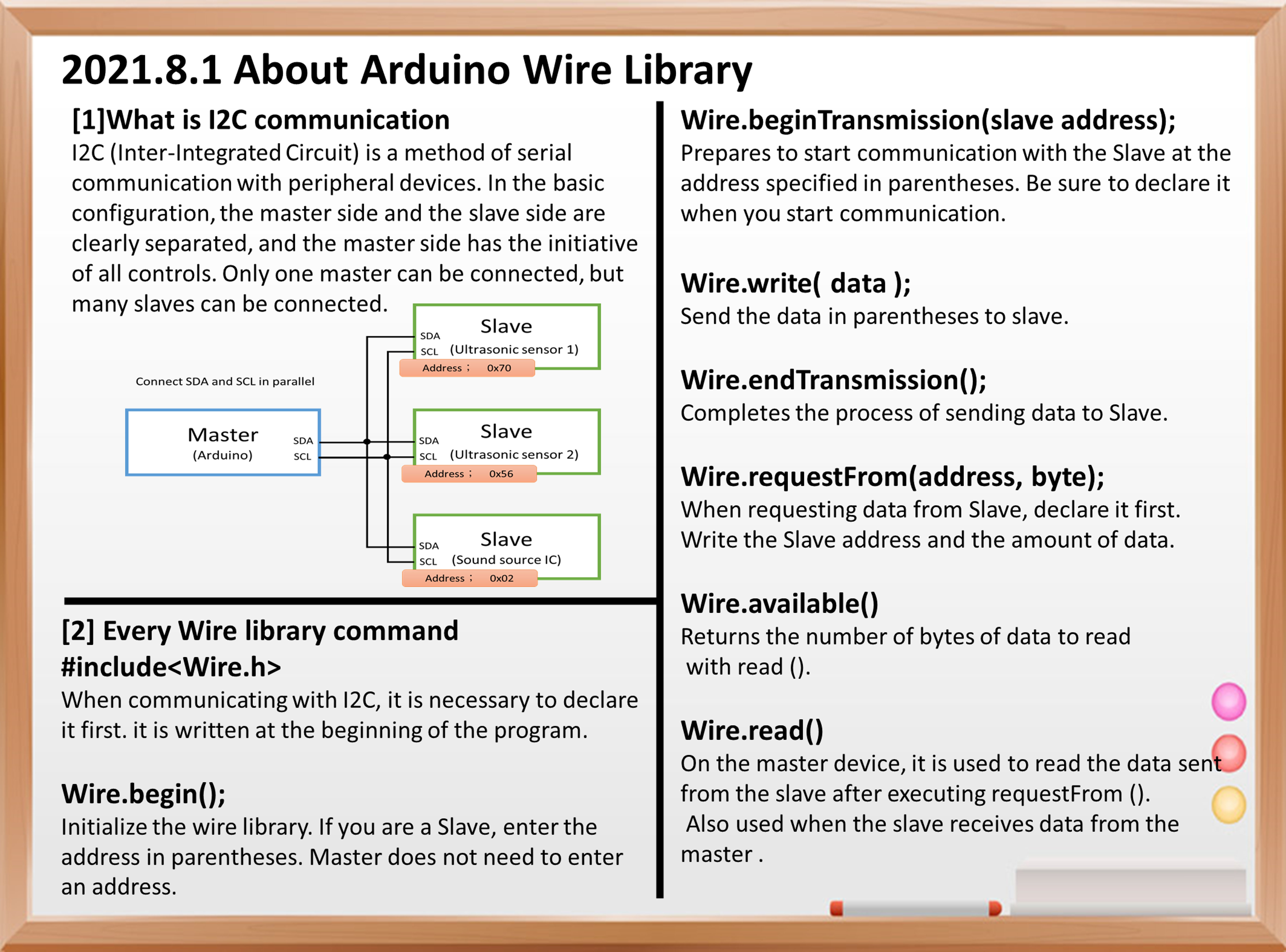
Main commands of the Wire library
#include<Wire.h>
When communicating with I2C, it is necessary to declare it first. This is a statement that says “use the Wire library” and is written at the beginning of the program.
Wire.begin();
Initialize the wire library. If you are a Slave, enter the address in parentheses. Master does not need to enter an address.
Wire.beginTransmission(slave address);
Prepares to start communication with the Slave at the address specified in parentheses. Be sure to declare it when you start communication.
Wire.write( data );
The data in parentheses of “Wire.write” is sent to the address specified in “Wire.beginTransmission”. Basically, the data is within 1 byte.
Wire.endTransmission();
Completes the process of sending data to Slave. In the Wire library, the data buffer from “begin Transmission” to “end Transmission” is 32 bytes, so if there is a lot of data to be transmitted, it is necessary to divide it by “end Transmission” sequentially.
Wire.requestFrom(address, byte);
When the Master requests data from Slave, it declares it first. Write the request destination address and the amount of data you want.
Wire.available()
Returns the number of bytes that can be read by read ().
Wire.read()
On the master device, it is also used when reading the data sent from the slave after executing “requestFrom ()” and when the slave receives the data from the master.
I2C programs for ultrasonic sensors
Here is the ultrasonic sensor program I talked about in my previous blog. In my last blog, I’ll focus on the areas of communication that I didn’t really touch on.
   #include <Wire.h>

    void setup()
    {
      Wire.begin();                // join i2c bus (address optional for master)
      Serial.begin(9600);          // start serial communication at 9600bps
      pinMode(11,OUTPUT);

    }

    int reading = 0;
    int SPEAKER = 11;
      int TIME=100;
      int m[9]={262,294,330,349,392,440,494,524,0 };
      int melody=0;

    void loop()
    {


      // step 1: instruct sensor to read echoes

      Wire.beginTransmission(112); // transmit to device #112 (0x70)
      Wire.write(byte(0x00));      // sets register pointer to the command register (0x00)
      Wire.write(byte(0x51));      // command sensor to measure in "centimeters" (0x51)
      Wire.endTransmission();      // stop transmitting

      // step 2: wait for readings to happen
      delay(20);                   // datasheet suggests at least 65 milliseconds

      // step 3: instruct sensor to return a particular echo reading
      Wire.beginTransmission(112); // transmit to device #112
      Wire.write(byte(0x02));      // sets register pointer to echo #1 register (0x02)
      Wire.endTransmission();      // stop transmitting

      // step 4: request reading from sensor
      Wire.requestFrom(112, 2);    // request 2 bytes from slave device #112

      // step 5: receive reading from sensor
      if (2 <= Wire.available())   // if two bytes were received
      {
        reading = Wire.read();  // receive high byte (overwrites previous reading)
        reading = reading << 8;    // shift high byte to be high 8 bits
        reading |= Wire.read(); // receive low byte as lower 8 bits
        Serial.print(reading);   // print the reading
        Serial.println("cm");

        if(reading>105){

        }else if(reading>95){
          melody=m[7];
          tone(11,melody) ;
          delay(TIME);
        }else if(reading>85){
         melody=m[6];
         tone(11,melody) ;
         delay(TIME);
        }else if(reading>75){
         melody=m[5];
        tone(11,melody) ;
         delay(TIME);
        }else if(reading>65){
          melody=m[4];
        tone(11,melody) ;
          delay(TIME);

        }else if(reading>55){
          melody=m[3];
        tone(11,melody) ;
          delay(TIME);

        }else if(reading>45){
          melody=m[2];
        tone(11,melody) ;
          delay(TIME);

        }else if(reading>35){
          melody=m[1];
        tone(11,melody) ;
          delay(TIME);

        }else if(reading>25){
          melody=m[0];
        tone(11,melody) ;
          delay(TIME);

        }else if(reading>15){
          melody=m[8];
          tone(11,melody) ;
          delay(TIME);
        }
        tone(11,melody) ;

      }

      delay(5);                  // wait a bit since people have to read the output :)
    }
First, “#include ” and “Wire.begin ();” are included in “voidsetup () {“. Reads the Wire library and initializes the Wire library.
   #include <Wire.h>

    void setup()
    {
      Wire.begin();                // join i2c bus (address optional for master)
      Serial.begin(9600);          // start serial communication at 9600bps
      pinMode(11,OUTPUT);

    }
The main program consists of 5 stages.
First, specify the address (112) of the Slave device in “Wire.beginTransmission (112);”. Next, send 0x00 with “Wire.write”. This is a signal to start communication with an ultrasonic sensor. Then write 0x51. This sets the distance of the ultrasonic sensor to be read out later to be returned in centimeters. Send by “Wire.end Transmission”.
After waiting for 20 milliseconds, send 0x02. It requires the sensor to send an ultrasound reading. Then, use “Wire.requestForm” to prepare for reception. The capacity is 2 bytes. Finally, the flow is to read the measured value with “Wire.read ()”.
 // step 1: instruct sensor to read echoes
      Wire.beginTransmission(112); // transmit to device #112 (0x70)
      // the address specified in the datasheet is 224 (0xE0)
      // but i2c adressing uses the high 7 bits so it's 112
      Wire.write(byte(0x00));      // sets register pointer to the command register (0x00)
      Wire.write(byte(0x51));      // command sensor to measure in "centimeters" (0x51)
      // use 0x51 for centimeters
      // use 0x52 for ping microseconds
      Wire.endTransmission();      // stop transmitting


      // step 2: wait for readings to happen
      delay(20);                   // datasheet suggests at least 65 milliseconds


      // step 3: instruct sensor to return a particular echo reading
      Wire.beginTransmission(112); // transmit to device #112
      Wire.write(byte(0x02));      // sets register pointer to echo #1 register (0x02)
      Wire.endTransmission();      // stop transmitting


      // step 4: request reading from sensor
      Wire.requestFrom(112, 2);    // request 2 bytes from slave device #112


      // step 5: receive reading from sensor
      if (2 <= Wire.available())   // if two bytes were received
      {
        reading = Wire.read();  // receive high byte (overwrites previous reading)
        reading = reading << 8;    // shift high byte to be high 8 bits
        reading |= Wire.read(); // receive low byte as lower 8 bits
        Serial.print(reading);   // print the reading
        Serial.println("cm");
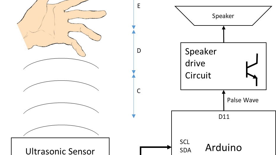
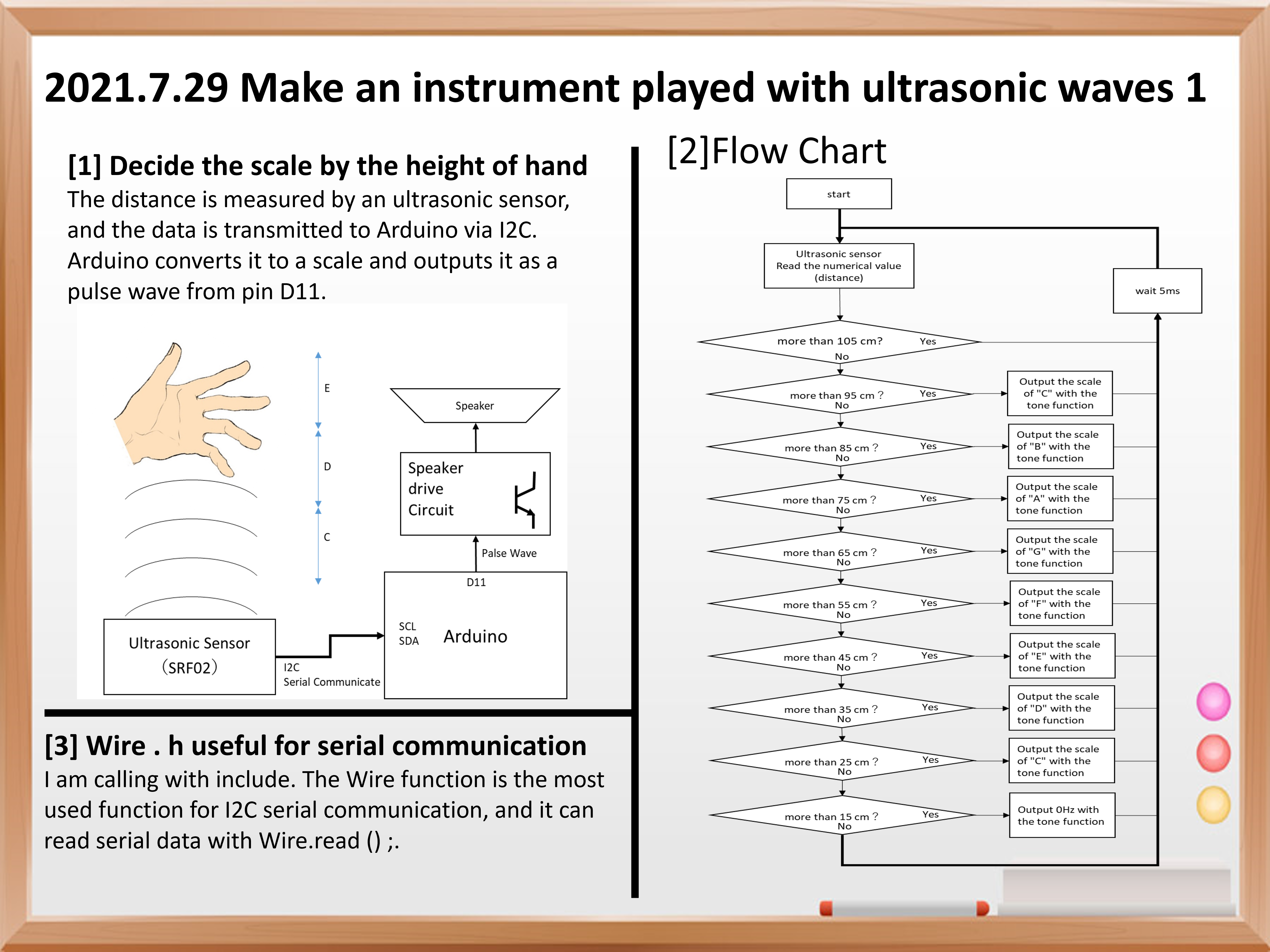
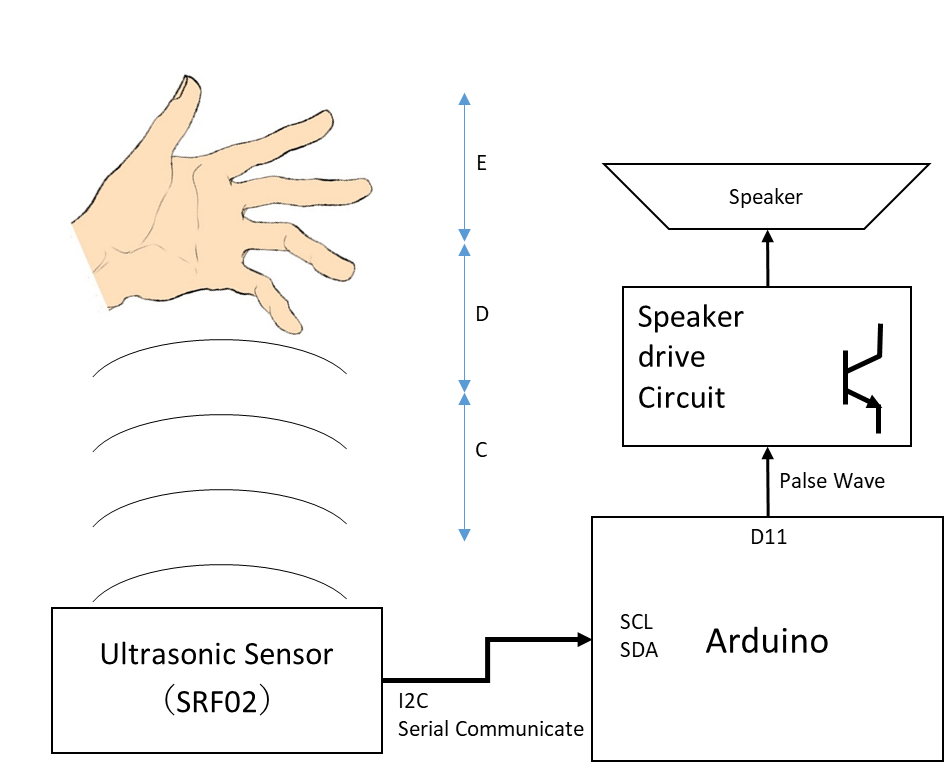
Suddenly, I want to make an instrument that can be played with ultrasonic waves.
As shown in the figure on the right, the design image is to place the ultrasonic sensor facing up and hold your hand over it to play.
The scale is determined by the height of the hand you hold.
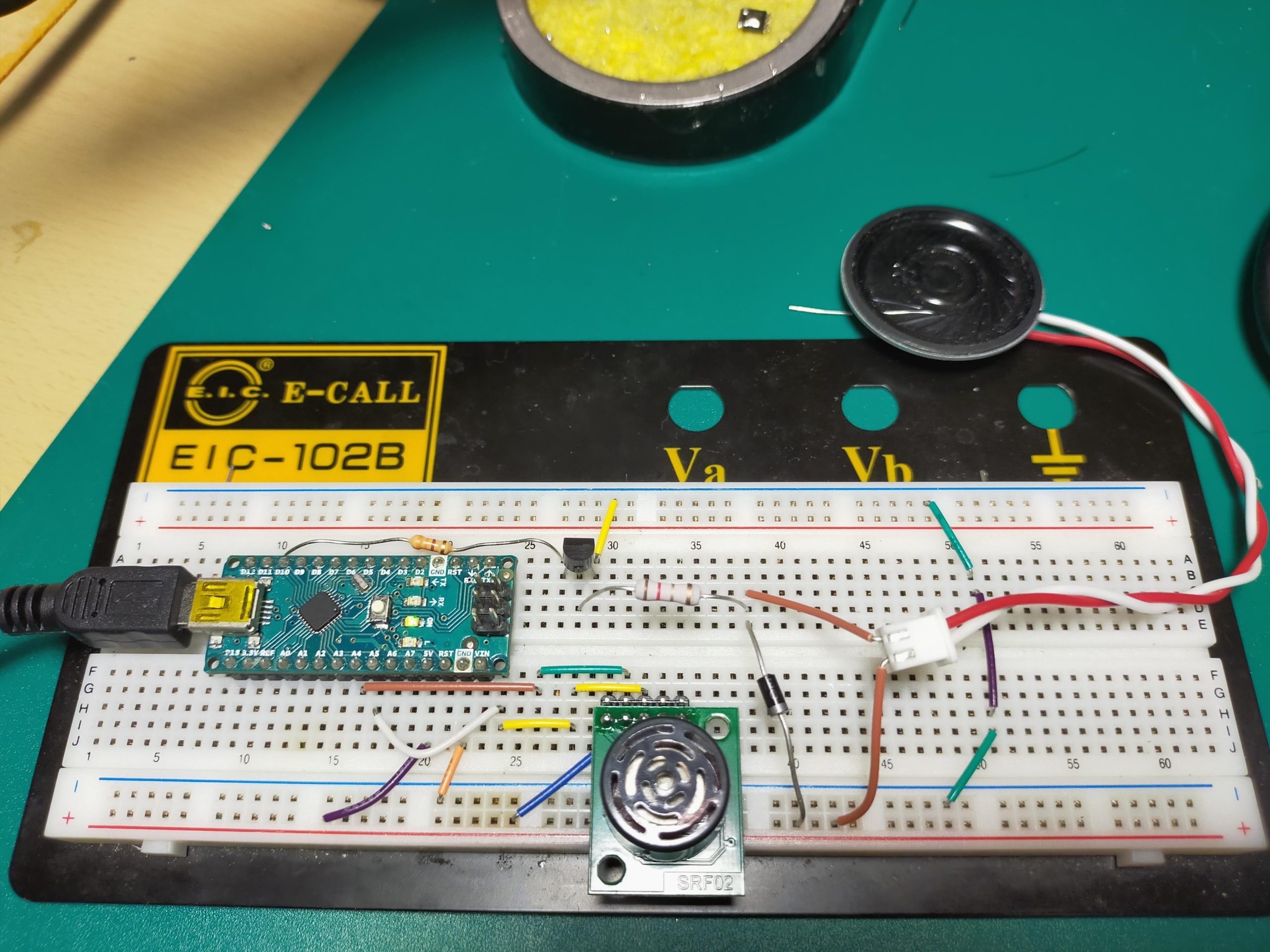
Next, consider the musical instrument system. The ultrasonic sensor uses SRF-02, which was introduced in the previous blog. Also, the circuit that outputs sound from the microcomputer uses the speaker drive circuit that I wrote in the previous blog.
The figure on the right is a simple system diagram.
The ultrasonic sensor SRF02 outputs the detected distance via I2C serial communication or UART.
This time, I decided to use I2C, which is easy to wire.
The distance is numerically input from the ultrasonic sensor to the Arduino via I2C.
The numerical value is processed in Arduino, converted into sound scale data, and output to the speaker.
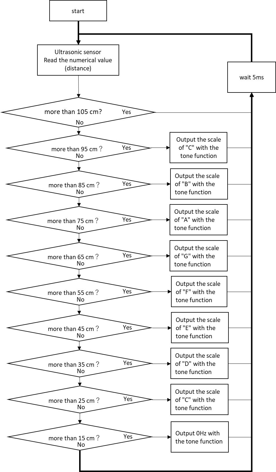
Next, I wrote a flowchart to design the program below.
When start the program, it first reads the value of the ultrasonic sensor.
The ultrasonic sensor then returns a number in centimeters of the distance to the hand you hold it over.
In Arduino, the condition is branched by an if statement that is layered on top of each other, and the frequency of each scale is assigned.
Next, the processing in the “if tatement” is explained.
First, determine if the height is 105 cm or more. If the height is 105 cm or more, the program and scale will be maintained as they are.
In other words, it continues the scale mentioned above. Since 105 cm is quite high, it is assumed that you are not holding it up.
Next, if 105 cm or more is No, the next step is to determine whether it is 95 cm or more. If it is 95 cm or more, it means that the hand is between 95 cm and 105 cm, so the scale of do is output.。
Then, if it is 85 cm or more, it branches to Shi, if it is 75 cm or more, it branches to La, and finally, if it is 15 cm or more, it becomes the lower do.
After outputting each scale, the process returns to the beginning and starts over from reading the sensor value.
If you convert this to the code of the program, it will be as follows.
  #include <Wire.h>

    void setup()
    {
      Wire.begin();                // join i2c bus (address optional for master)
      Serial.begin(9600);          // start serial communication at 9600bps
      pinMode(11,OUTPUT);
    }
    int reading = 0;
    int SPEAKER = 11;
    int TIME=100;
    int m[9]={262,294,330,349,392,440,494,524,0 };
    int melody=0;

    void loop()
    {
      // step 1: instruct sensor to read echoes
      Wire.beginTransmission(112); // transmit to device #112 (0x70)
      // the address specified in the datasheet is 224 (0xE0)
      // but i2c adressing uses the high 7 bits so it's 112
      Wire.write(byte(0x00));      // sets register pointer to the command register (0x00)
      Wire.write(byte(0x51));      // command sensor to measure in "centimeters" (0x51)
      // use 0x51 for centimeters
      // use 0x52 for ping microseconds
      Wire.endTransmission();      // stop transmitting
      // step 2: wait for readings to happen
      delay(20);                   // datasheet suggests at least 65 milliseconds
      // step 3: instruct sensor to return a particular echo reading
      Wire.beginTransmission(112); // transmit to device #112
      Wire.write(byte(0x02));      // sets register pointer to echo #1 register (0x02)
      Wire.endTransmission();      // stop transmitting
      // step 4: request reading from sensor
      Wire.requestFrom(112, 2);    // request 2 bytes from slave device #112
      // step 5: receive reading from sensor
      if (2 <= Wire.available())   // if two bytes were received
      {
        reading = Wire.read();  // receive high byte (overwrites previous reading)
        reading = reading << 8;    // shift high byte to be high 8 bits
        reading |= Wire.read(); // receive low byte as lower 8 bits
        Serial.print(reading);   // print the reading
        Serial.println("cm");

        if(reading>105){
        }else if(reading>95){
          melody=m[7];
          tone(11,melody) ;
          delay(TIME);
        }else if(reading>85){
         melody=m[6];
         tone(11,melody) ;
         delay(TIME);
        }else if(reading>75){
         melody=m[5];
        tone(11,melody) ;
         delay(TIME);
        }else if(reading>65){
          melody=m[4];
        tone(11,melody) ;
          delay(TIME);

        }else if(reading>55){
          melody=m[3];
        tone(11,melody) ;
          delay(TIME);

        }else if(reading>45){
          melody=m[2];
        tone(11,melody) ;
          delay(TIME);

        }else if(reading>35){
          melody=m[1];
        tone(11,melody) ;
          delay(TIME);

        }else if(reading>25){
          melody=m[0];
        tone(11,melody) ;
          delay(TIME);

        }else if(reading>15){
          melody=m[8];
          tone(11,melody) ;
          delay(TIME);
        }
        tone(11,melody) ;
      }
      delay(5);                  // wait a bit since people have to read the output :)
   }
Here, the new function is the wire function.
#include<Wire.h>
I am calling with include. The Wire function is the most used function for I2C serial communication, and it can read serial data with Wire.read () ;.
I didn’t know this function either, but it seems to be a little deeper, so I hope I can post it all together at a later date.