In the previous blog, I even designed a block diagram of an ultrasonic musical instrument.
I will start circuit design at once.
The following is the block diagram designed last time.
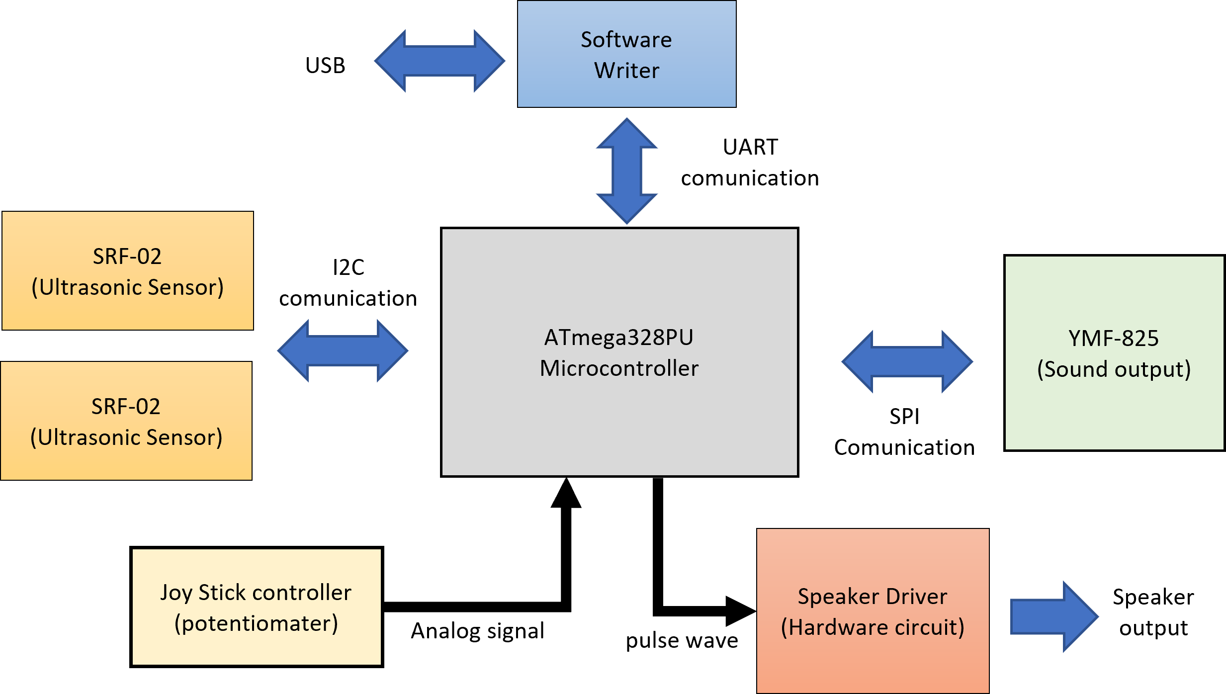
In short, how to connect each module to the microcomputer is important.
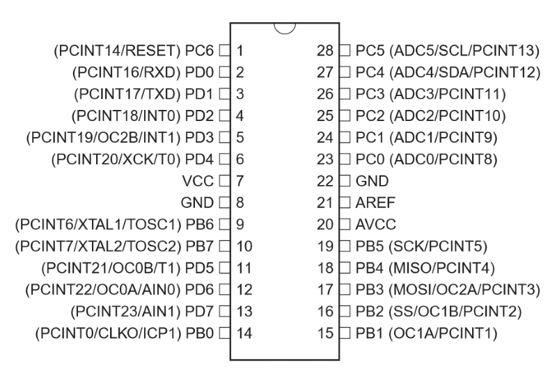
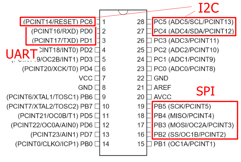
First, check the pin layout of the microcomputer to be used.
Connected to SRF-02
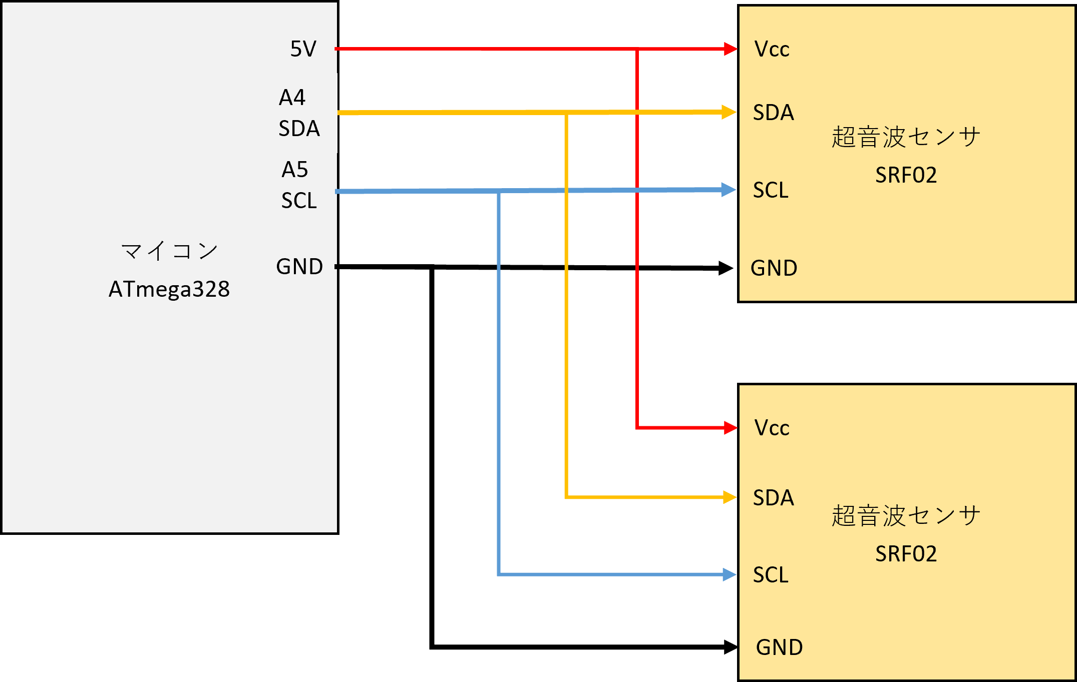
SRF-02 communicates in the format of I2C.
I2C connection method is very easy. This time, we will make it possible to connect two ultrasonic sensors in parallel.
For I2C communication, connect the four terminals of Vcc and GND power supply terminals, synchronous clock SCL, and signal line SDA of the sensor (Slave) and microcomputer (Master), respectively.
Even if they are connected in parallel, there is no problem because the addresses are assigned to each sensor.
Connected to YMF-825
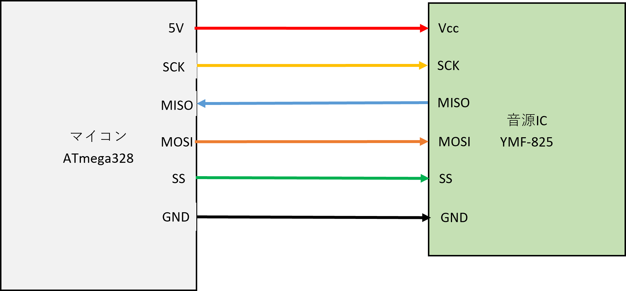
YMF-825 communicates by SPI.
SPI communication is from Vcc and GND power terminals on the sound source IC (Slave) and microcomputer (Master), SS (Slave Select) that selects the SCK of the synchronization clock and the Slave to be connected, and from Master to Slave. There are MOSI (Master Out Slave In) that sends a signal and MISO (Master In Slave Out) that sends a signal from Slave to Master, and it consists of a total of 6 lines.
Software Writer
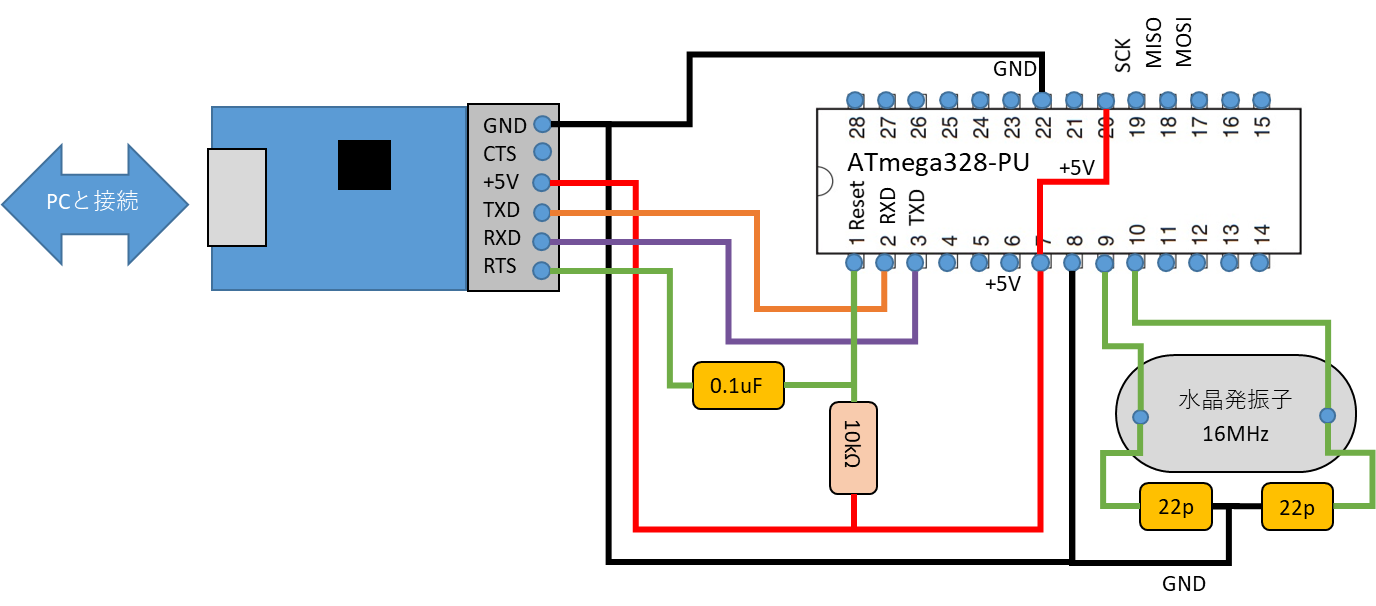
Software writing is I introduced it in the previous blog .
Since soft writing communicates via UART, connect the TXD (transmission) of the converter to the RXD (receive) of the ATmega328, and connect the RXD (receive) of the converter to the TXD (transmission) of the ATmega328. After that, the + 5V and GND of the TTL converter are also supplied to the ATmega328. Then, connect the RTS and the ATmega328 Reset via a 0.1uF capacitor so that the converter can send a reset signal.
Speaker Driver
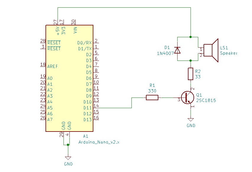
Depending on how you use YMF-825, you may run out of memory. For such a case, we have prepared a speaker driver circuit that can produce simple electronic sounds.
Finally, I wrote a circuit diagram that integrates these circuits.
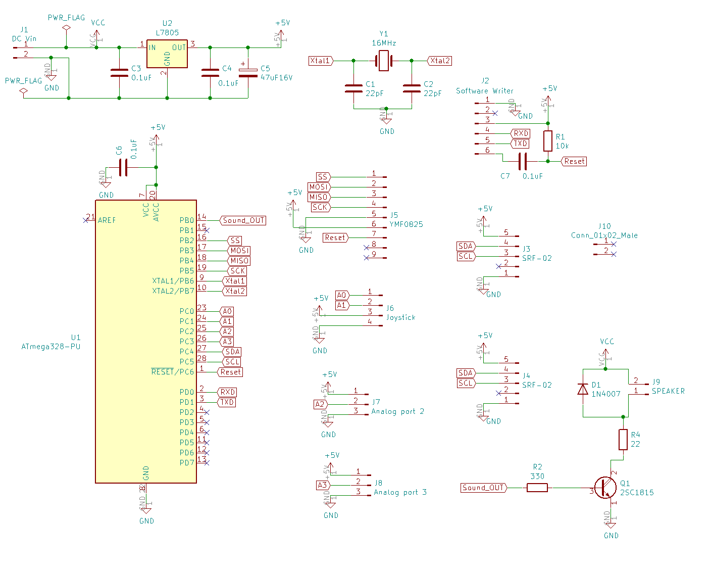
Next time, I will design the board with KiCad.