

This time, I investigated the command of the ultrasonic sensor SRF-02.
First , there are two modes of communication of SRF-02, I2C and UART, Now I focus on I2C.
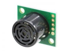
the main features of SRF-02.
◆ Main specifications
・ Microcomputer : 16F687-I / ML
・ Measurement range: 16cm ~ 6m
・ Power supply: 5V (current consumption 4mA Typ.)
・ Frequency used: 40KHz.
– Analog gain: 64 levels of automatic gain control
-Connection mode: Mode 1 = I2C, Mode 2 = Serial bus
・ Fully automatic adjustment function: No calibration required after turning on the power
・ Distance measurement timing: Echo time measurement, task control by host
・Unit of measurement: μS (microseconds), millimeters, inches
・ Size: 24mmx20mmx17mm
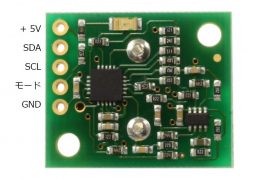
・ Input / output terminal: 5 pins
・ Weight: 4.6 grams
Main commands of SRF-02
Next are the main commands used by SRF-02.
The communication method of the command uses the Arduino Wire library for communication. For details, see Previous blog.
Communication method with I2C
To use F02 in I2C mode, open the mode pin.
For I2C communication, up to 16 can be connected in parallel. Since they are connected in parallel, addresses are assigned to each Slave (ultrasonic sensor).
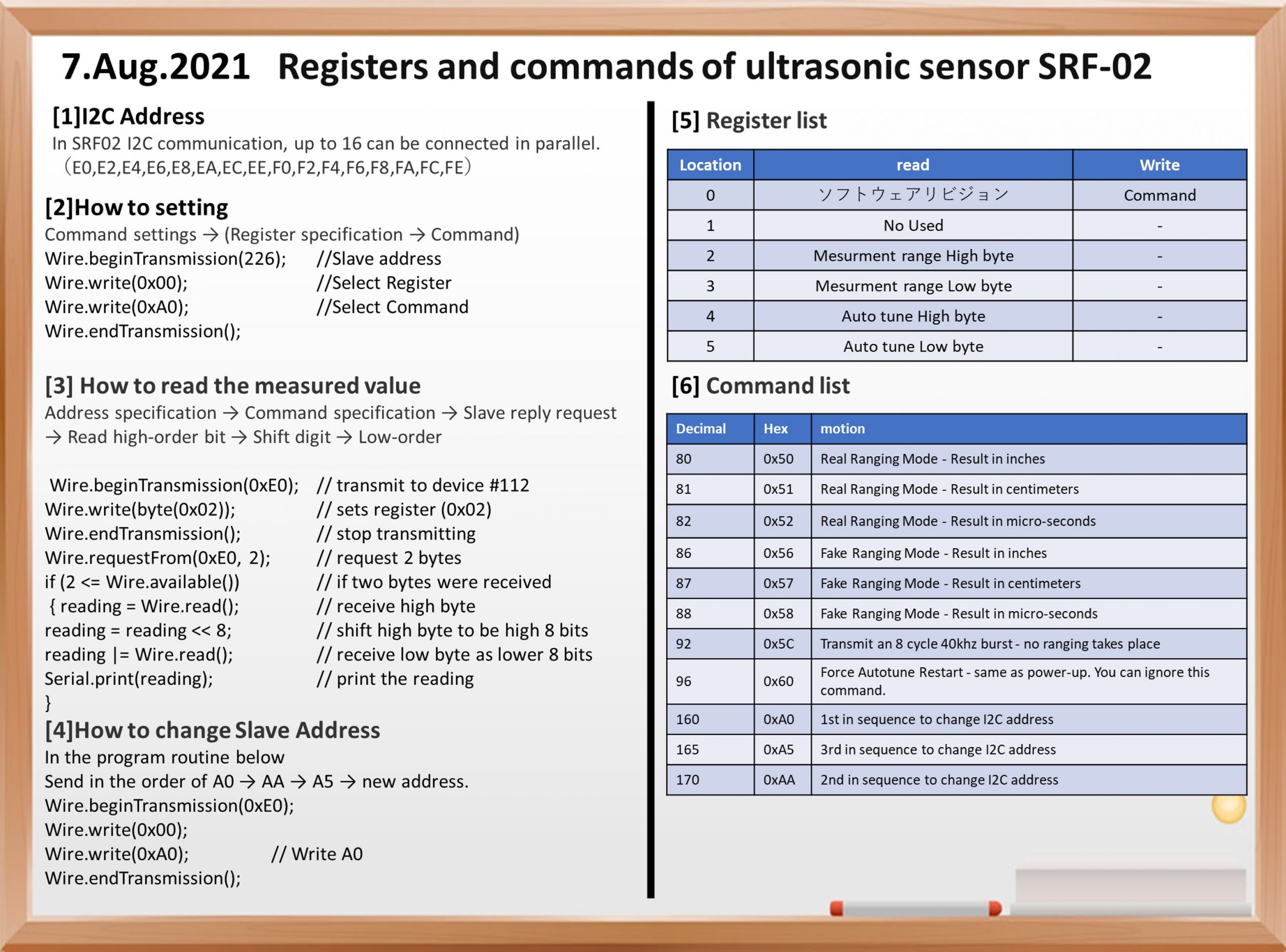
The factory address for SRF02 is 0xE0. The address can be changed by the user, and up to 16 addresses (E0, E2, E4, E6, E8, EA, EC, EE, F0, F2, F4, F6, F8, FA, FC, FE) are used. can.
register
The SRF-02 has 6 types of registers.
| Location | Read | Write |
| 0 | Software rivision | Command Register |
| 1 | No Used | – |
| 2 | Sense Range High byte | – |
| 3 | Sense Range Low byte | – |
| 4 | smallest Auto tune-High byte | – |
| 5 | smallest Auto tune Low byte | – |
Of the 6 registers, only register 0 can be written from Master.
Various settings of SRF-02 can be made by putting a numerical value in the 0th register.
When reading from 0, the software revision is returned. The first is an unused pin.
The 2nd and 3rd registers are the registers that return the measured values. The measured value is returned with a maximum capacity of 2 bytes. Since one register is 1 byte, two registers (2,3) are required. This measurement is returned in inches, centimeters, microseconds, etc., depending on the settings.
In other words, if you specify 0 at the beginning, then you can refer to the measured value in the 2nd and 3rd registers.
Command of SRF-02
The following is the command specified for SRF-02 No. 0.
| Decimal | Hex | motion |
| 80 | 0x50 | Real Ranging Mode – Result in inches |
| 81 | 0x51 | Real Ranging Mode – Result in centimeters |
| 82 | 0x52 | Real Ranging Mode – Result in micro-seconds |
| 86 | 0x56 | Fake Ranging Mode – Result in inches |
| 87 | 0x57 | Fake Ranging Mode – Result in centimeters |
| 88 | 0x58 | Fake Ranging Mode – Result in micro-seconds |
| 92 | 0x5C | Transmit an 8 cycle 40khz burst – no ranging takes place |
| 96 | 0x60 | Force Autotune Restart – same as power-up. You can ignore this command. |
| 160 | 0xA0 | 1st in sequence to change I2C address |
| 165 | 0xA5 | 3rd in sequence to change I2C address |
| 170 | 0xAA | 2nd in sequence to change I2C address |
If necessary, write the above command to the first command register, wait for the required time, and read the result. The echo buffer is cleared at the beginning of each range. The range lasts up to 66msec. After this, the measured value is read from the 2nd and 3rd registers.
How to Command to SRF-02
What should I do when instructing SRF-02 from Master?
The following is a program to set the measured value to cm for reference.
Wire.beginTransmission(226); //Select slave address
  Wire.write(0x00);    //select register
  Wire.write(0xA0);  //select command
  Wire.endTransmission();
First, specify the Slave address (226) with Wire.beginTransmission (226) ;.
The next thing to send is the register to connect. If you want to make any settings,
Send 0 with Wire.write (0x00); to access register 0.
Next, what you send is the command to set.
For example, if you want to set the measured value to be returned in cm, you can send the command 0x51.
Wire.write (0x51);
This completes the settings, so Wire.endTransmission (); ends this communication.
Although it depends on the content of the command, the basic flow is to specify a register → send the command for that register.
Program to read the measured value of SRF-02
Next is the method of reading the measured value from SRF-02.
      Wire.beginTransmission(0xE0); // transmit to device #112
      Wire.write(byte(0x02));      // sets register pointer to echo #1 register (0x02)
      Wire.endTransmission();      // stop transmitting


      Wire.requestFrom(0xE0, 2);    // request 2 bytes from slave device #112

      if (2 <= Wire.available())   // if two bytes were received
      {
        reading = Wire.read();  // receive high byte (overwrites previous reading)
        reading = reading << 8;    // shift high byte to be high 8 bits
        reading |= Wire.read(); // receive low byte as lower 8 bits
        Serial.print(reading);   // print the reading
        Serial.println("cm");
      }
First, when reading a numerical value from SRF-02, access the second register 0x02. That is the program up to the third line.
Next, prepare to receive data from SRF-02. That is Wire.requestFrom (0xE0, 2) ;.
This means that it will receive 2 bytes of data from Slave at address E0.
After that, you can receive the data with Wire.read () ;. However, since it has 2 bytes, the lower bits will be overwritten if it is received as it is. Therefore, first receive the data of the upper 8 bits (reading = Wire.read ();), shift the reading bit to (reading = reading & lt; & lt; 8;) 8 bits higher, and then skip to the next. The incoming number (lower bit) is received by (reading = Wire.read ();).
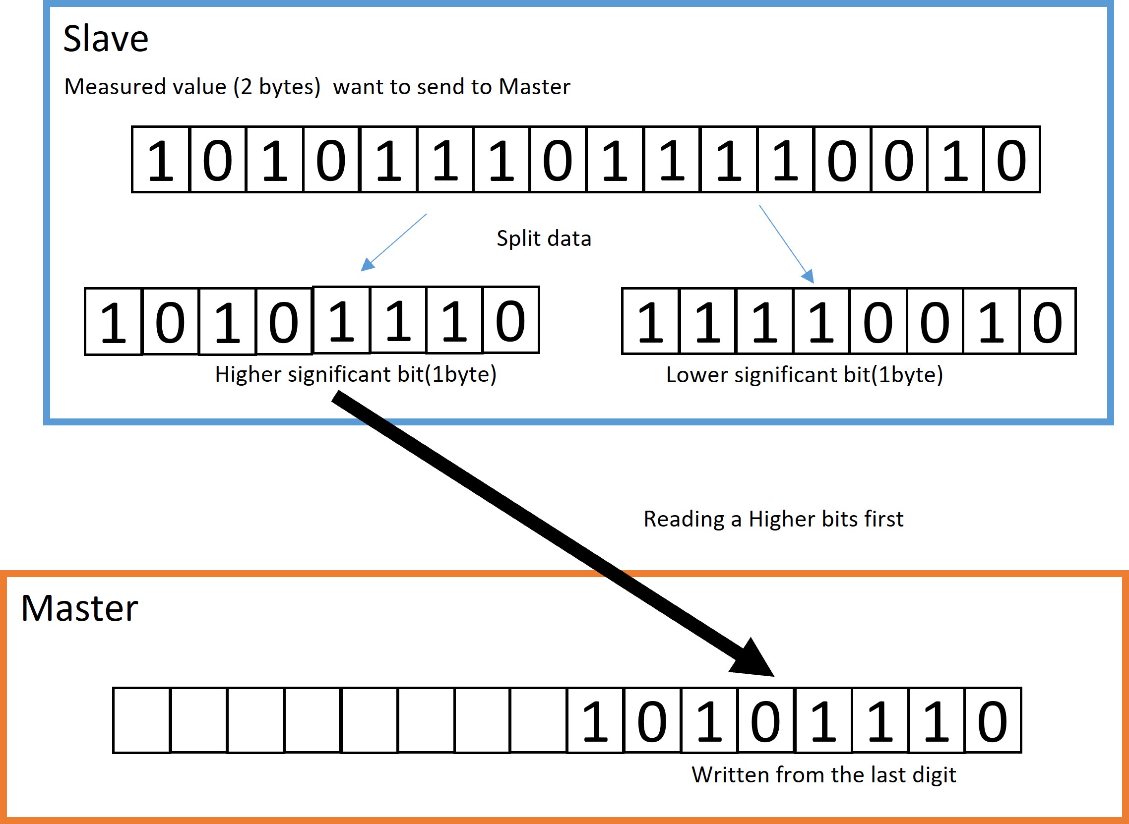
The data divided by Slave is written from the high-order bit.
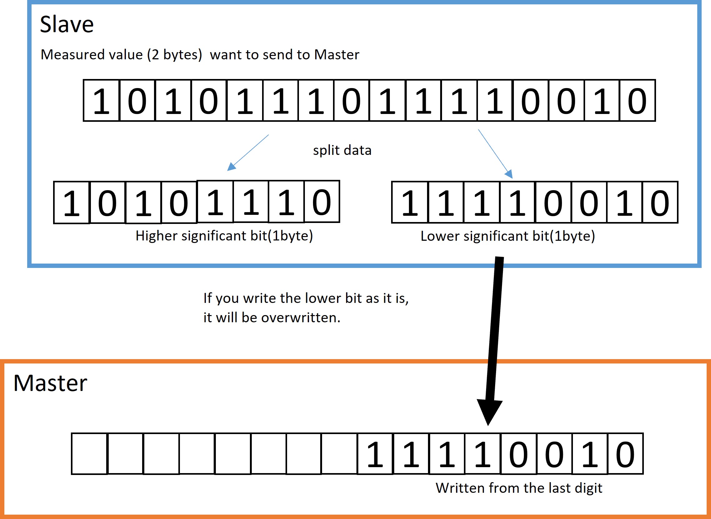
If you write the lower bit as it is, it will be overwritten.

Therefore, the first written high-order bit is shifted up to 8 bits.
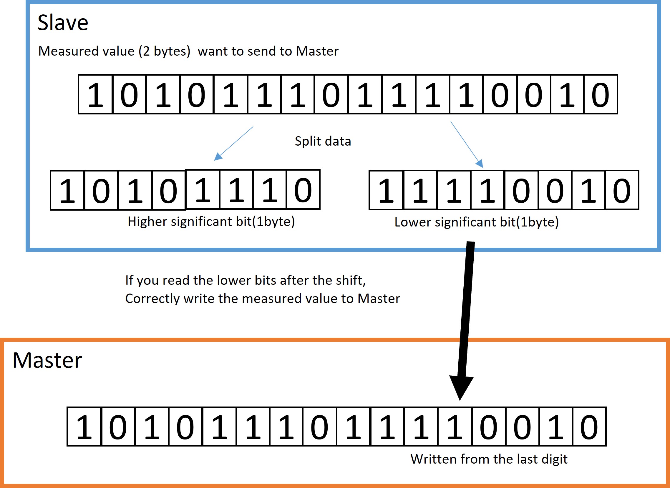
After that, if you write the lower bits, everything can be sent correctly.
How to SRF-02 addressing
Next is the SRF-02 addressing procedure. The method is simple, send the above commands 0xA0, 0xAA, 0xA5, in order, and finally send a new address to enter the mode to specify the address. For example, if you want to return from the original address E0 to the new address F4, run the following program. It’s very simple, isn’t it?
  Wire.beginTransmission(0xE0);
  Wire.write(0x00);
  Wire.write(0xA0);               //Write A0
  Wire.endTransmission();

  Wire.beginTransmission(0xE0);
  Wire.write(0x00);
  Wire.write(0xAA);               //Write AA
  Wire.endTransmission();

  Wire.beginTransmission(0xE0);
  Wire.write(0x00);
  Wire.write(0xA5);               //Write A5
  Wire.endTransmission();

  Wire.beginTransmission(0xE0);
  Wire.write(0x00);
  Wire.write(0xF4);               //Write new address F4
  Wire.endTransmission();
That’s all for today.
2021.8.7 Hiiragi