

When making an ultrasonic musical instrument, I came to think that it would be better if various sounds could be output.
what is YMF-825
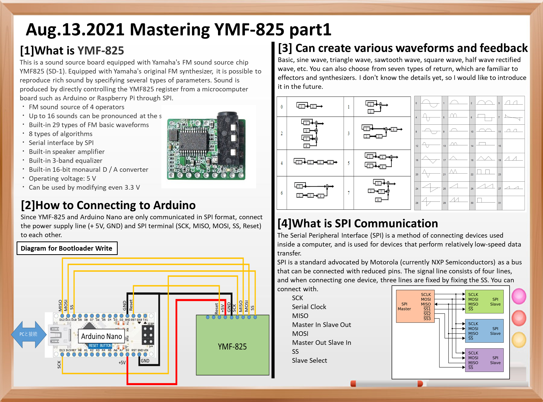
Yamaha FM sound source chip YMF825 (SD-1) It is a sound source board equipped with . Equipped with Yamaha’s original FM synthesizer, it is possible to reproduce rich sound by specifying several types of parameters.
Sound is produced by directly controlling the YMF825 register from a microcomputer board such as Arduino or Raspberry Pi through SPI. Since it also has a speaker amplifier, there is no need to prepare an amplifier circuit separately.
* Although it is equipped with a 3.5 mm headphone jack, earphones that use 4-pole CTIA such as for iPhone cannot be used (OMTP ones can be used). ** From Switch science’s sales page **
Specifications
- 4 operator FM sound source
- Up to 16 sounds can be produced at the same time
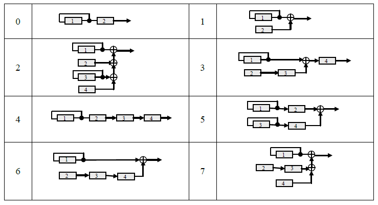
- 29 types of FM basic waveforms built-in, 8 types of algorithms
- SPI Serial interface by
- Built-in speaker amplifier
- Built-in 3-band equalizer
- Built-in 16-bit monaural D / A converter
- Operating voltage: 5 V
- 3.3 V can also be used by modifying

A sample sketch is posted on GitHub, so I used it as a reference.
Any waveform can be created
The sample sketch also includes a simple manual.
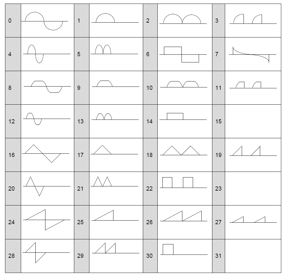
Basic, sine wave, triangle wave, sawtooth wave, square wave, half wave rectified wave, etc.
7 types of return can be applied
You can also choose from seven types of return, which are familiar to effectors and synthesizers.
I don’t know the details yet, so I would like to introduce it in the future.
What is SPI Communication
The Serial Peripheral Interface (SPI) is a method of connecting devices used inside a computer, and is used for devices that perform relatively low-speed data transfer.
SPI is a standard proposed by Motorola (currently NXP Semiconductors) as a pin-saving bus.
The signal line consists of 4 lines, and when connecting one device, it can be connected with 3 lines by fixing the SS.
SCK
Serial Clock
MISO
Master In Slave Out
MOSI
Master Out Slave In
SS
Slave Select

Simple operation circuit example
Next is the connection diagram.
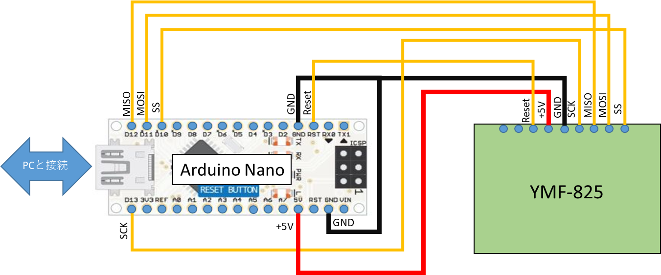
Since YMF-825 and Arduino Nano are only communicated in SPI format, connect the power supply line (+ 5V, GND) and SPI terminal (SCK, MISO, MOSI, SS, Reset) to each other.
That’s all for today