
We are planning a new project from this time.
Disassemble a commercial product and learn the technology hidden in it.
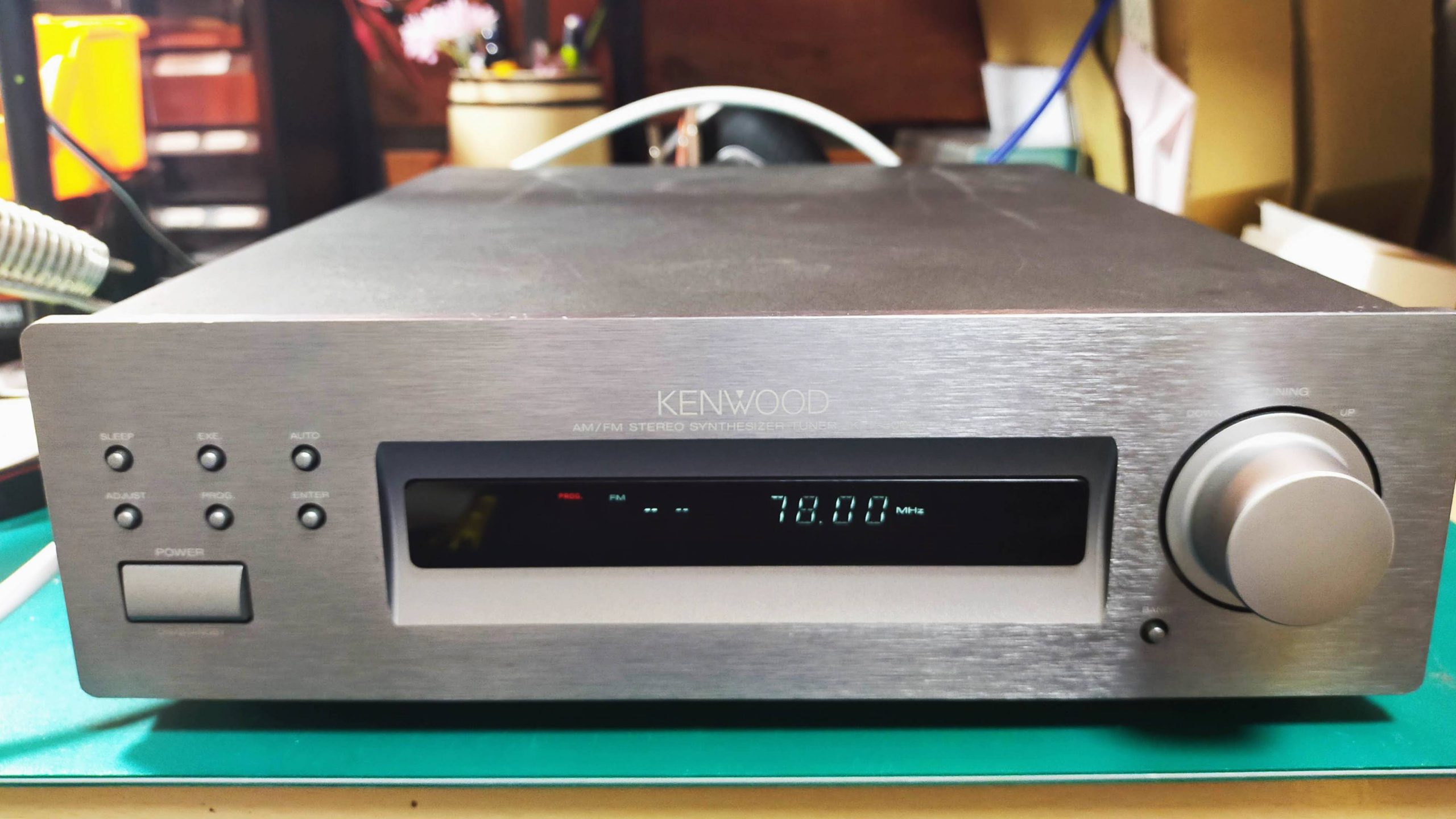
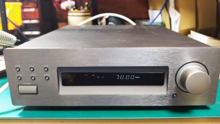
This time, I will disassemble the AM / FM radio tuner, KTF5002 made by KENWOOD.
This was sold at HARDOFF in the neighborhood for 1500 yen.
It was a junk item, but it was in good condition, and both FM and AM radios sounded fine.
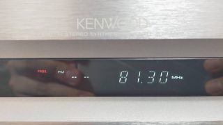
Can Receive FM radio
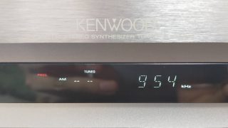
Can Receive AM radio
First of all, I investigated this radio.
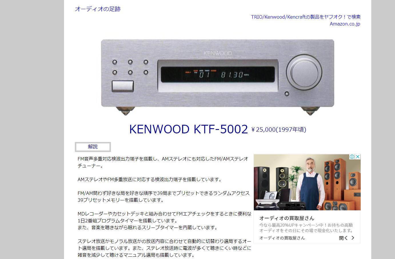
When I looked it up, it was released around 1997. It’s one below from my age.
The price is reasonable at 25,000 yen.
The pdf of the instruction manual was also included, so I will paste the link below.
This is a Specfication bellow.
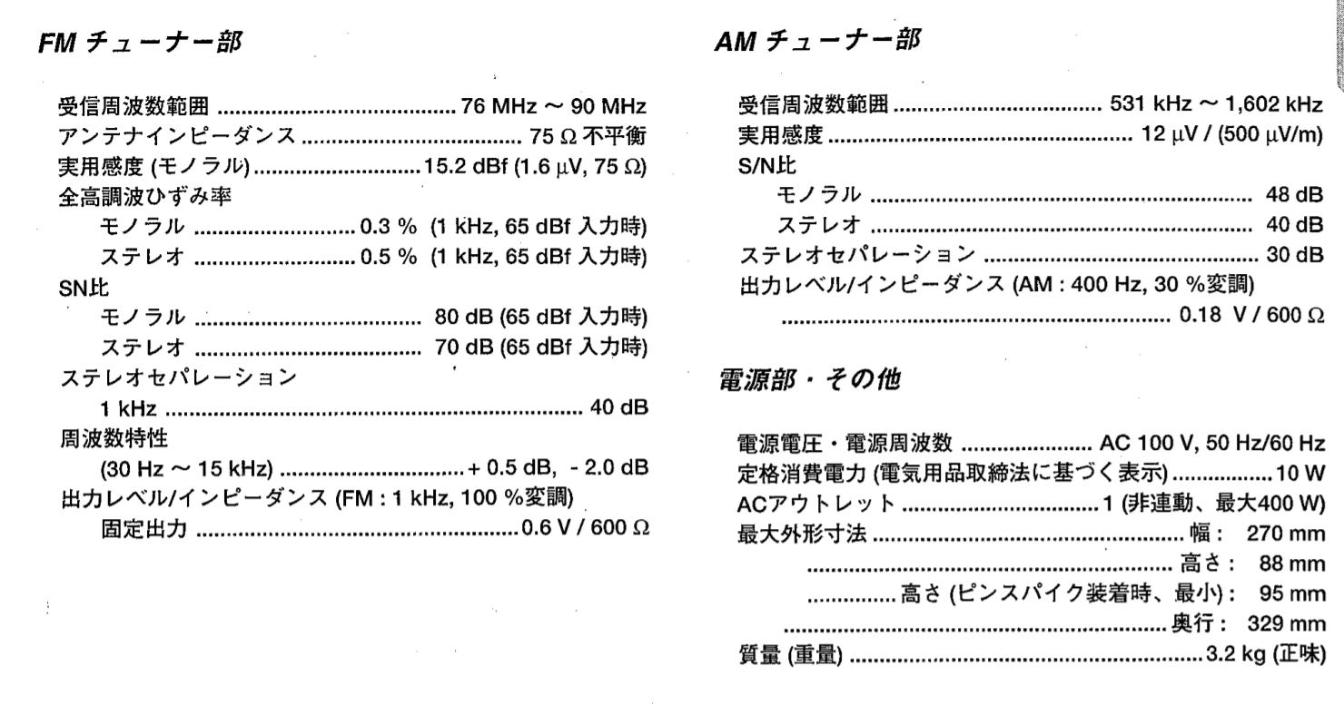
Reception frequency range of FM radio is 76MHz to 90MHz. It is enough range for FM radio at that time.
Over 90MHz was the band of analog TV audio signals. Currently, this vacant band is the complementary broadcast of AM radio (WideFM).Total harmonic distortion is 0.5%, which is reasonable for audio equipment.
What surprised me personally was that the SN ratio of the FM radio was 70 dB. I think the performance is quite high for that time.
In addition, the SN ratio of AM is 40 dB. After all, AM radio has more noise than FM.
Front panel
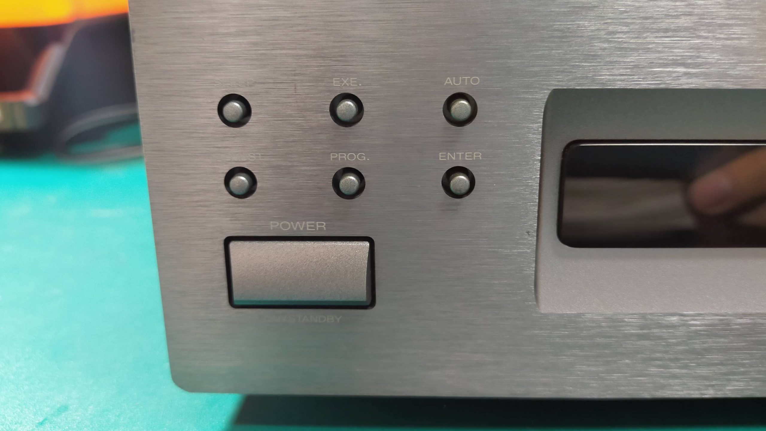
It seems that you can set Auto (automatic tuning), sleep, time reservation, etc.
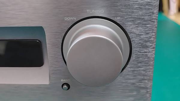
At first glance, I thought it was a volume, but this is a channel selection. You can’t spin it around, just tilt it.
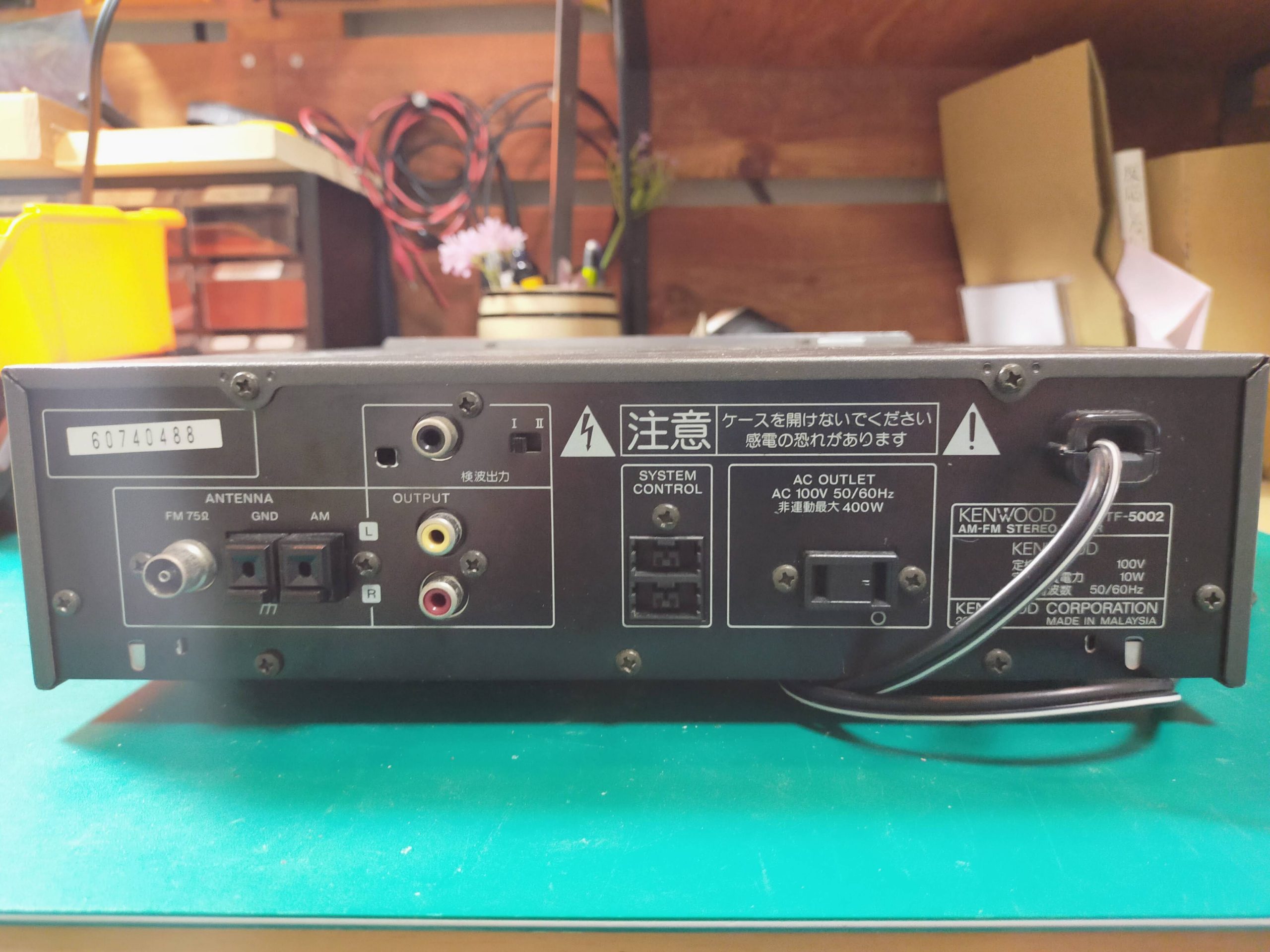
The back is like this. There are FM antenna terminal, AM antenna terminal, audio output, outlet, and detection output. The FM antenna terminal is the same as the TV antenna wire.
Let’s remove the cover and take a look at the contents.
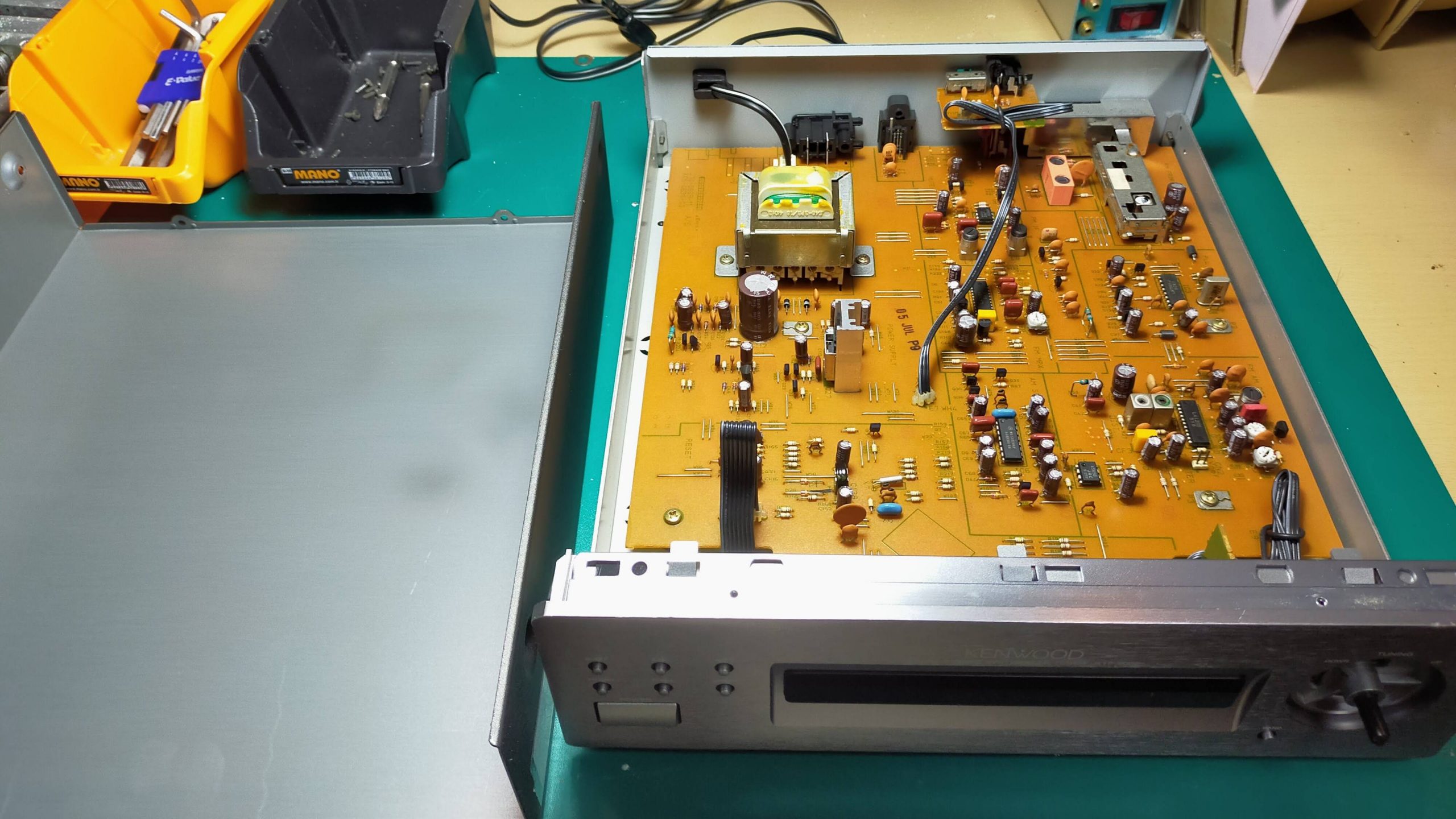
I see. I thought it was complicated, but the contents were contained in one board.
Take out the board further.
Roughly, the name of the circuit is shown.
It consists of many circuits such as FM front end, FM multiplexer, AM stereo demodulation circuit, PLL circuit, power supply circuit, etc. I will explain these circuits one by one in future blogs.
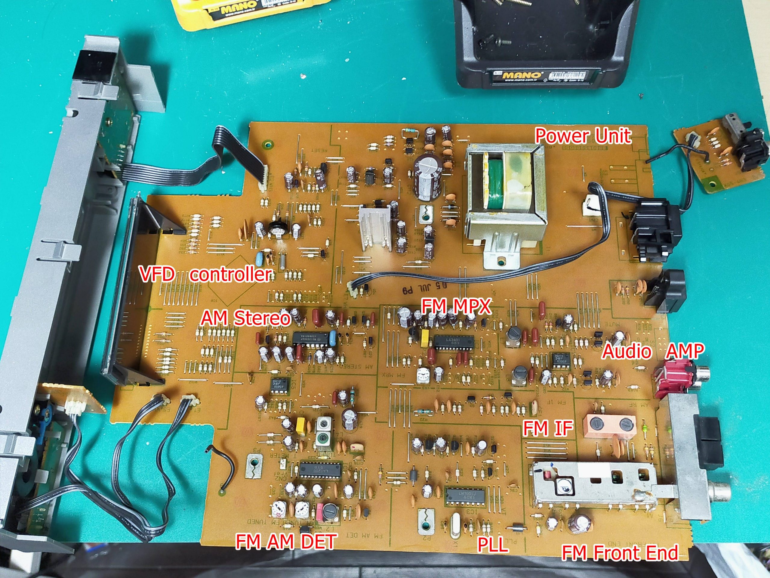
Today, I just disassembled it, so I will focus on the entire board.
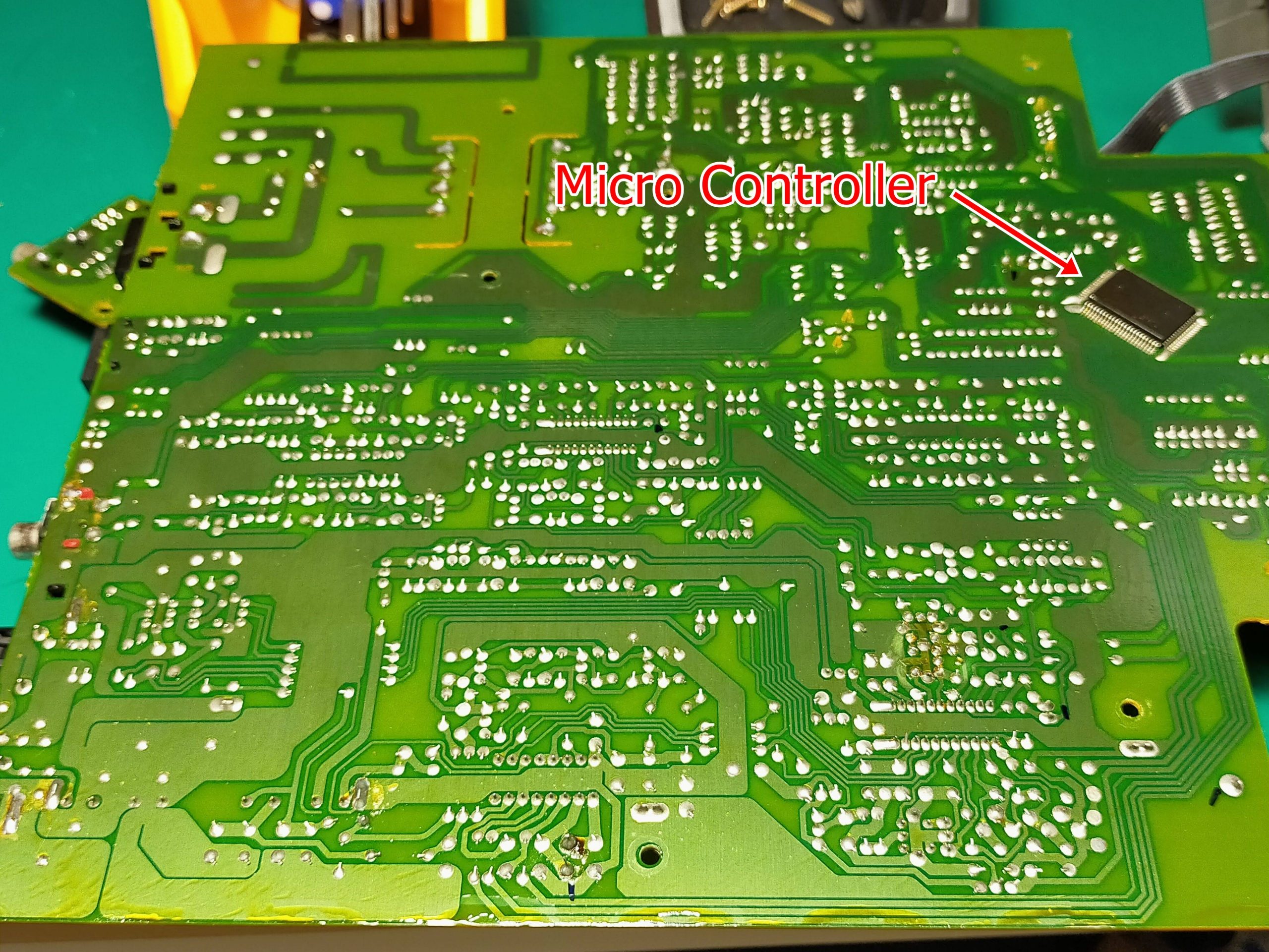
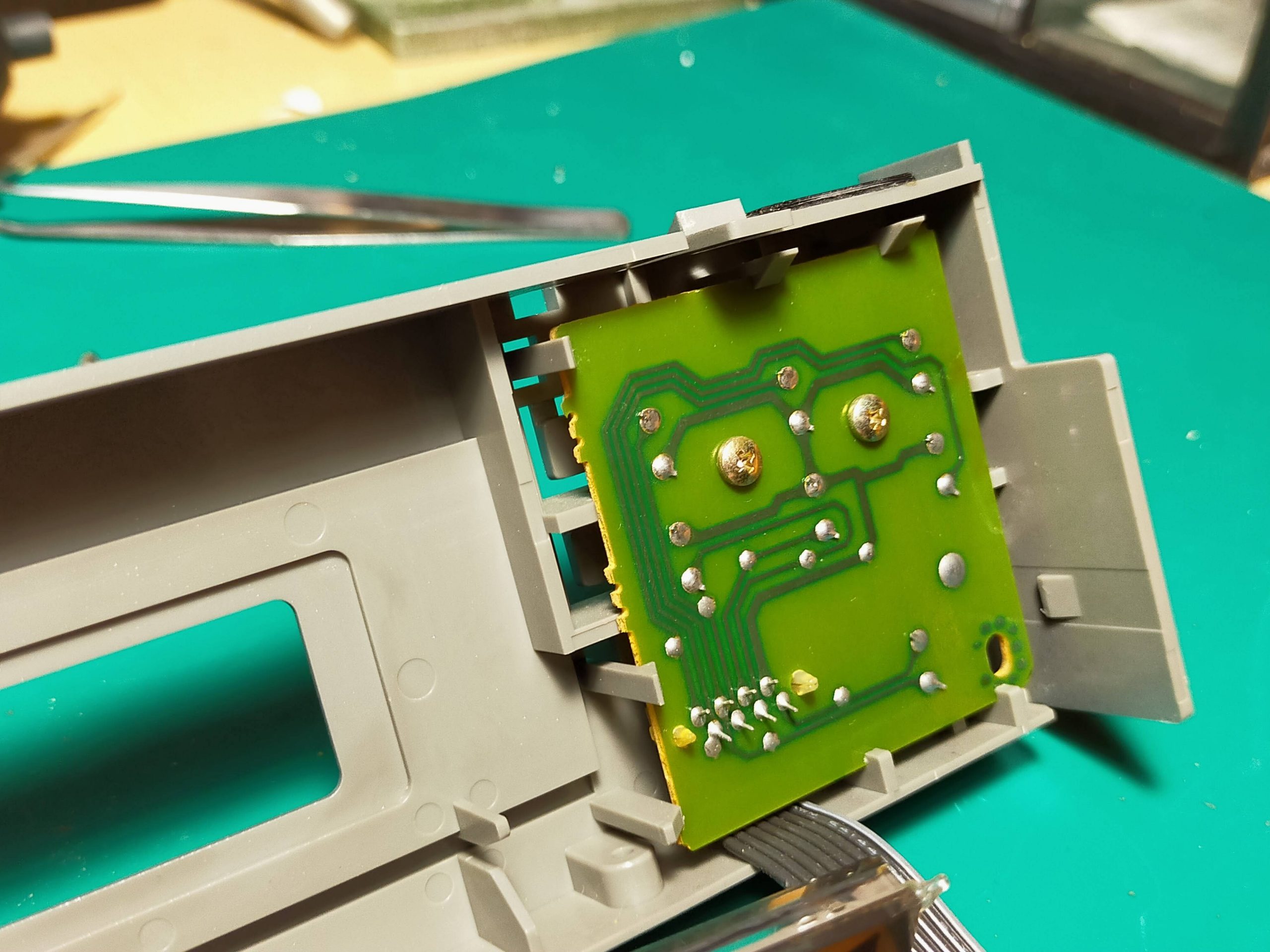
First, the material of the substrate is a paper phenol substrate. It’s cheap and not very durable, but it’s good enough for stationary audio equipment. The board has a one-sided single-layer structure, and the parts are attached to only one side. Therefore, jumper lines are often used because of the intersection of lines. In addition, the surface mount components are only the microcomputer (thick, …) attached to the back surface, and all the rest are discrete components. All of this part is manually inserted, where the legs of the part are bent behind the board. And you can see that it is cut by human hands.
Also, since there is no unevenness in the soldering, it can be seen that the board is applied to the solder bath and the soldering is done by the flow method. Only the microcomputer may be retrofitted and reflowed with cream solder.
Honestly, I think that this is a considerable labor cost from the current era.
I think it’s amazing that this is sold for 25,000 yen.
Also, the power supply circuit is also noteworthy.
Audio-related equipment is so heavy because it does not use a switching method in the power supply circuit. Switching power supplies are, for example, mobile phone chargers and personal computer charging adapters. If you use switching, the circuit of this radio will be lighter, but switching will generate a lot of noise, so if you use it as a power supply for the radio, the SN ratio will drop at once. Therefore, there is no choice but to place a large transformer and make it with an old-fashioned power supply circuit.
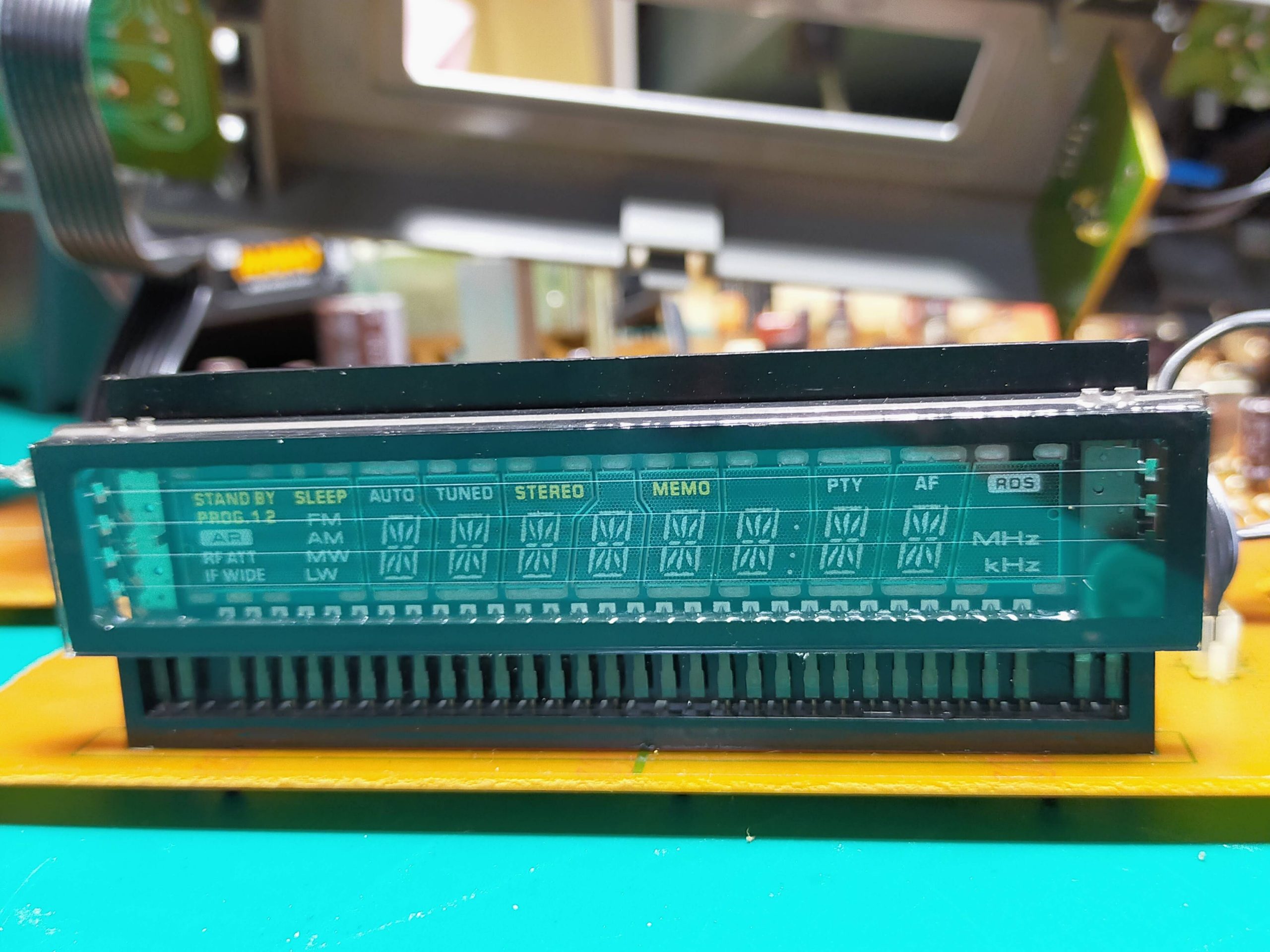
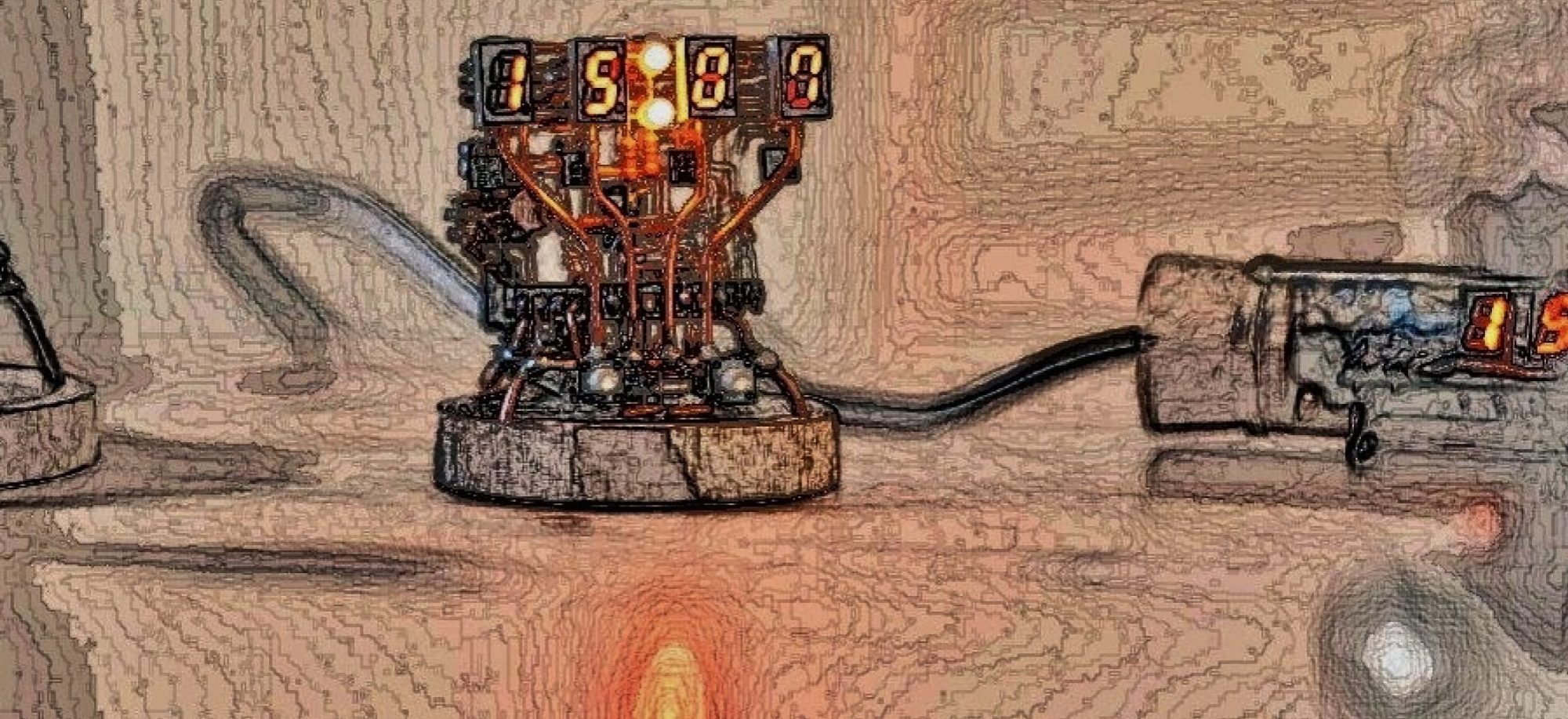
In addition, the display is a display method called VFD. Often, at the supermarket cashier, the pale letters “Gokei 2350 En” appear. Nowadays, there are many liquid crystal displays (calculators, etc.) and LEDs, but this is an old-fashioned display that applies vacuum tube technology.
I hope I can write this in detail in future blogs.
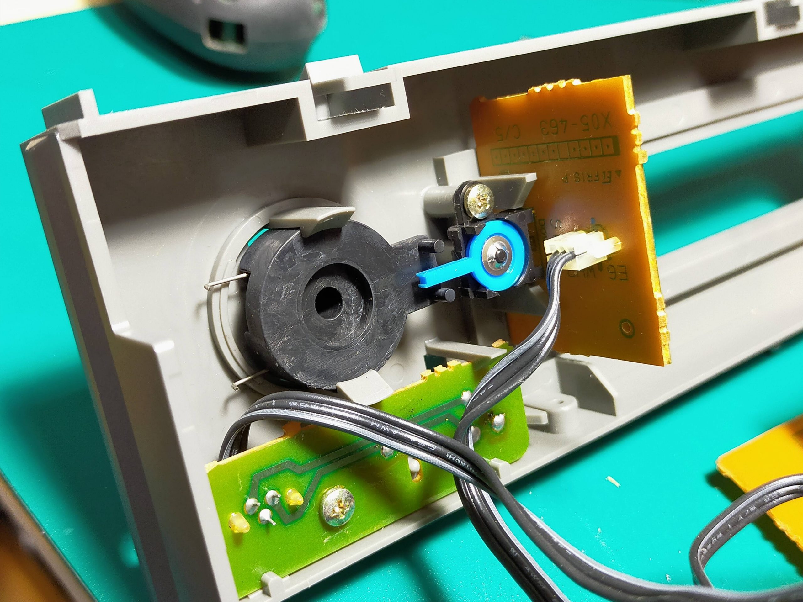
Finally, the back side of the switches. It was pretty simple.
Today was a roughly disassembled report. In the future, I would like to analyze this product in more detail with the following plan. Next time, I will explain the reception principle of AM radio and FM radio on 9/2. I will also touch on the story of PLL and MPX.
Current serialization; “Disassembly survey of FM / AM stereo tuner KTF-5002”
| Update | Content |
| 8/26 | I disassembled KTF5002 (specifications, disassembly procedure, board configuration, mechanism) |
| 9/2 | AM / FM radio reception principle (AM / FM is the main reception method used, what is PLL / MPX) |
| 9/9 | I investigated the IC used in KTF5002 |
| 9/16 | About FM front-end circuit, FM-IF circuit, AM-RF circuit |
| 9/23 | PLL circuit principle |
| 9/30 | About FM-AM DET circuit |
| 10/7 | About FM-MPX circuit |
| 10/14 | About Audio AMP circuit |
| 10/21 | About power supply circuit |
| 10/28 | About VFD display circuit |