
This is a new project from this time.
I would like to make a new musical instrument.
For this blog, I would like to do everything from the concept to the design of the block diagram.
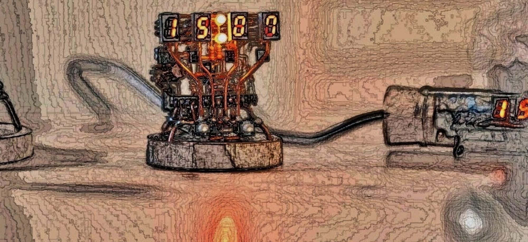
Image of new musical instrument
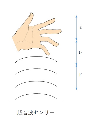
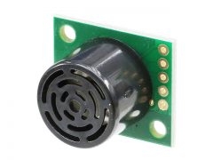
The image shows the ultrasonic sensor facing up as shown on the right.
Hold your hand over the sensor to play. It is a simple scale whose scale is determined by the height of the hand you hold it over.
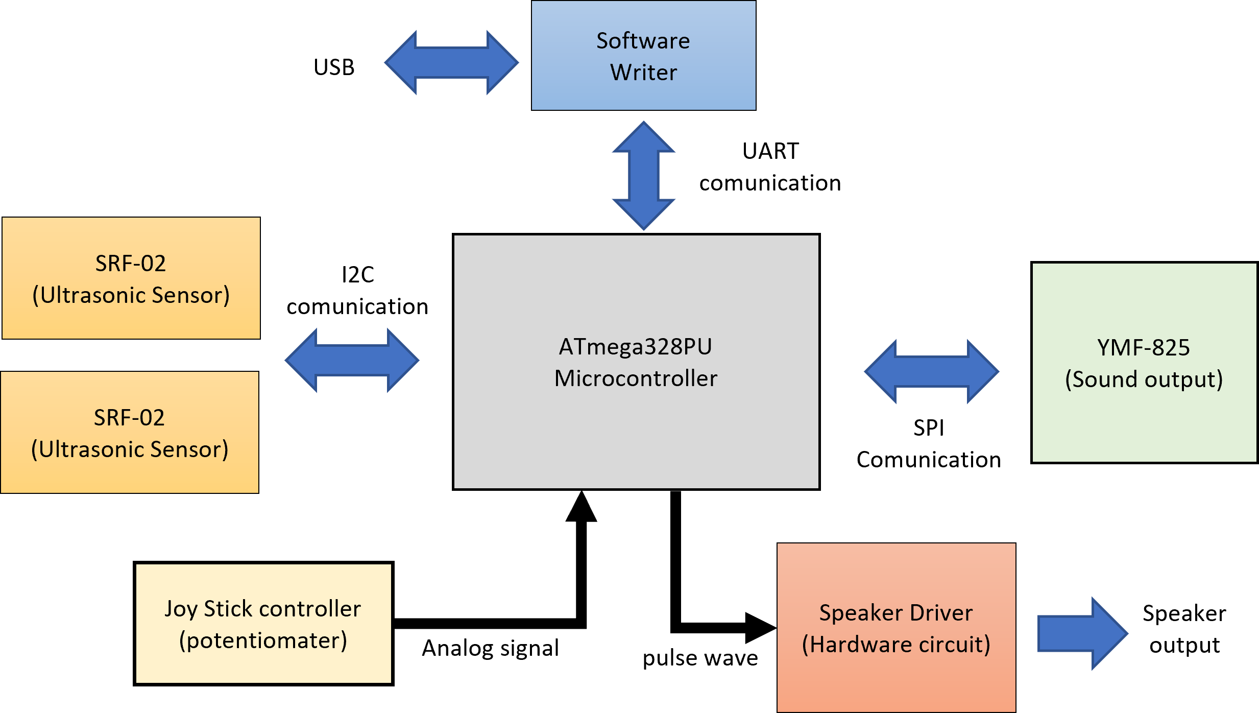
Block Diagram
Next is a block diagram.
The main microcomputer uses ATmega328 for the convenience of being easily programmed with Arduino.
SRF-02 was used for the ultrasonic sensor. Allows you to connect up to two sensors. Information is transmitted between the ultrasonic sensor and the microcomputer by I2C communication.
Also, connect the module YMF-825 that uses YAMAHA’s sound source IC that can create various tones.
This exchanges information via SPI communication.
After that, a joystick that allows you to manually enter the timing of making sounds.
And, in case the YMF-825 and the ultrasonic sensor cannot be operated at the same time due to the memory over of the microcomputer, etc.
It also has a circuit that can drive the speaker directly.
Also, since the microcomputer operates independently, it is necessary to prepare a software write terminal. Since it is still in the development stage, it will be possible to connect to the USB of the personal computer by UART communication so that the RAM value can be read.
Next, let’s take a closer look at each block.
Microcomputer
The microcomputers to be used are summarized below on the Akizuki Denshi sales page.


It is a memory doubled version of ATmega168. The one in which a program called a boot loader is written is one of the popular microcomputers in electronic work such as being installed in Arduino.
■ Main specifications
・ Series: ATMEGA
-Power supply voltage: 1.8-5.5V
・ Core: megaAVR
・ Core size: 8bit
・ Clock: 20MHz
-Program memory: 32kB
・ EEPROM: 1kB
・ RAM: 2kB
・ GPIO: 23pin
・ ADC: 6Ch
・ UART / USART: 1Ch
・ I2C: 1Ch
・ SPI: 1Ch
・ Timer: 3Ch
・ Oscillator: Built-in / external
・ Package: DIP28
It’s versatile and has a decent amount of memory.
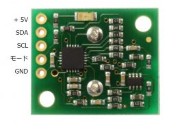
Ultrasonic Sensor(SRF-02)
First, there are two modes for SRF-02 communication, I2C and UART, but this time I focused on I2C.
First of all, the main features of SRF-02.
Please refer to the previous blog for details.
◆ Main specifications
・ Microcomputer used: 16F687-I / ML
・ Measurement range: 16cm ~ 6m.
・ Power supply: 5V (current consumption 4mA Typ.)
・ Frequency used: 40KHz.
-Analog gain: 64 levels of automatic gain control
-Connection mode: Mode 1 = I2C, Mode 2 = Serial bus
・ Fully automatic adjustment function: No calibration required after turning on the power
・ Distance measurement timing: Echo time measurement, task control by host
-Measurement unit: μS (microseconds), millimeters, inches
・ Size: 24mmx20mmx17mm
・ Input / output terminal: 5 pins
・ Weight: 4.6 grams
sound source IC(YMF-825)
Yamaha FM sound source chip YMF825 (SD-1) About the sound source board equipped with previous blog . Equipped with Yamaha’s original FM synthesizer, it is possible to reproduce rich sound by specifying several types of parameters.
Sound is produced by directly controlling the YMF825 register from a microcomputer board such as Arduino or Raspberry Pi through SPI. Since it also has a speaker amplifier, there is no need to prepare an amplifier circuit separately.
* Although it is equipped with a 3.5 mm headphone jack, earphones that use 4-pole CTIA such as for iPhone cannot be used (OMTP ones can be used). ** From Switch science’s sales page **

Specifications
- 4 operator FM sound source
- Up to 16 sounds can be produced at the same time
- 29 types of FM basic waveforms built-in, 8 types of algorithms
- SPI Serial interface by
- Built-in speaker amplifier
- Built-in 3-band equalizer
- Built-in 16-bit monaural D / A converter
- Operating voltage: 5 V
- 3.3 V can also be used by modifying it
Speker Driver Circuit
About the speaker drive circuit Previous blog for a summary.
Since this circuit is specialized for producing electronic sounds, I think that it is not suitable for playing ordinary music with this circuit.
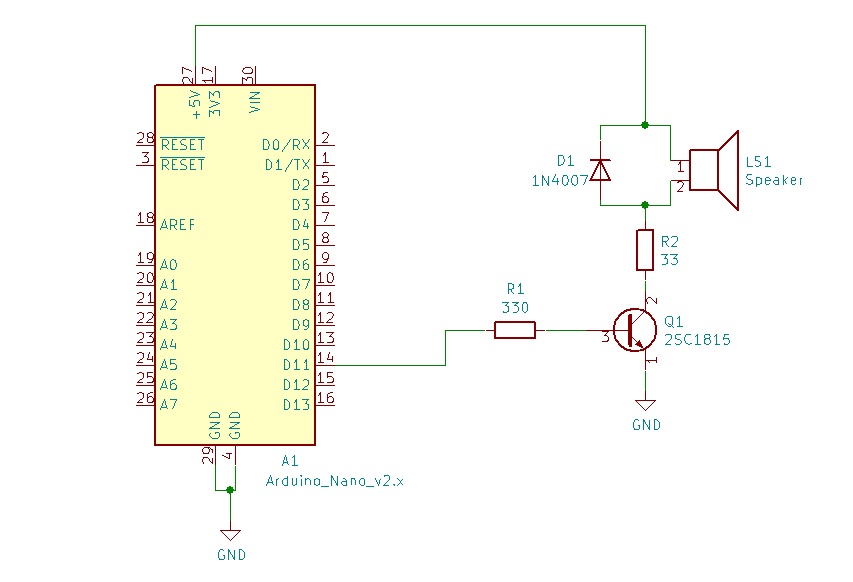
The circuit is very simple. A digital output square wave is output from Arduino. This digital signal is input to the base of transistor Q1. When a current is passed through the base, the collector-emitter is turned on and the current flows through the speaker. Depending on the HIGH / LOW cycle of the digital signal, whether or not current is passed through the speaker changes. Therefore, an electronic sound having a frequency of a digital signal is emitted from the speaker.
As for the resistor of R1, the current of the digital signal is too high for the base, so the current is reduced by sandwiching the resistor R1.
Also, since the DC current flowing through the speaker is too large for the R2 resistor, the current is reduced by sandwiching the R2 resistor.
Also, with the D1 diode, if the speaker coil is turned on and off with a square wave, the speaker voltage will jump up at once, so the voltage will not jump up and the current accumulated in the speaker coil will be transferred. It is loaded with a regenerative diode to escape.
Software Writing
Regarding soft writing, I also refer to the previous blog.
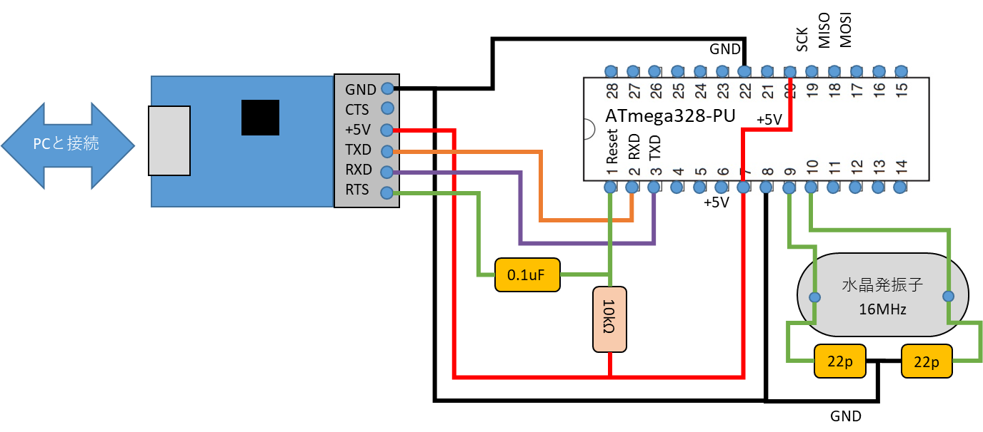
Since it is UART communication, connect the TXD (transmission) of the converter to the RXD (receive) of the ATmega328, and connect the RXD (receive) of the converter to the TXD (transmission) of the ATmega328. After that, the + 5V and GND of the TTL converter are also supplied to the ATmega328.
Then, connect the Reset of RTS and ATmega328 via a 0.1uF capacitor so that the converter can send a reset signal.
After that, connect a 16MHz crystal oscillator as the clock of ATmega328.
That’s all for today. Next time, I will start circuit design.