

This article is a continuation of the previous one.
Let’s get started to designing a PCB on the KiCad software.
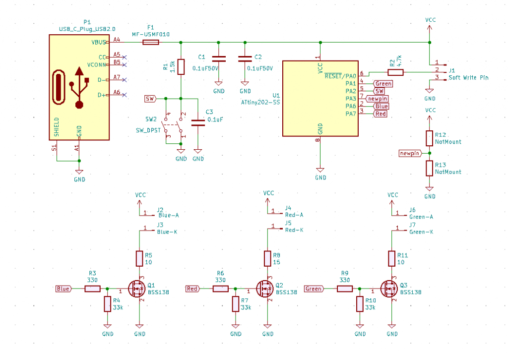
The designed circuit diagram is shown below.
Associate the footprint with reference from the schematic data.
Next, I will draw the wiring of the board. Need to know the size of the PCB.
Therefore, we designed the case first that wrote by 3D-CAD.
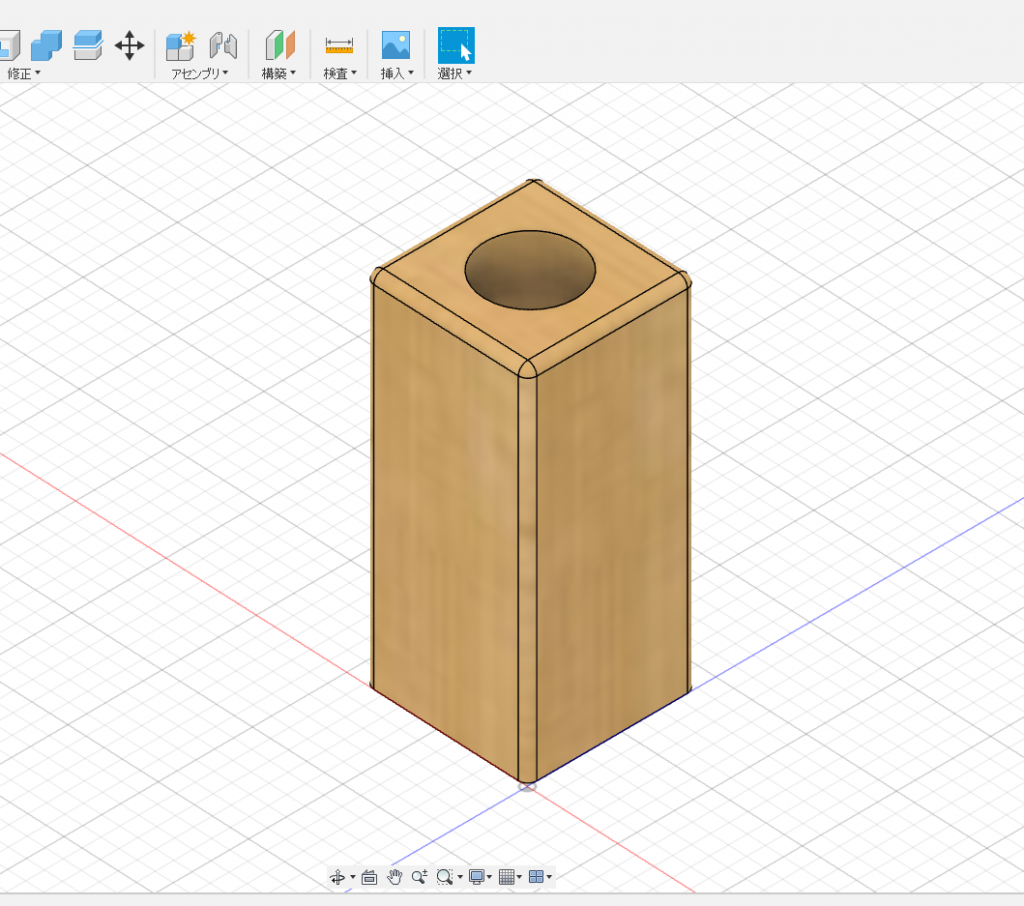
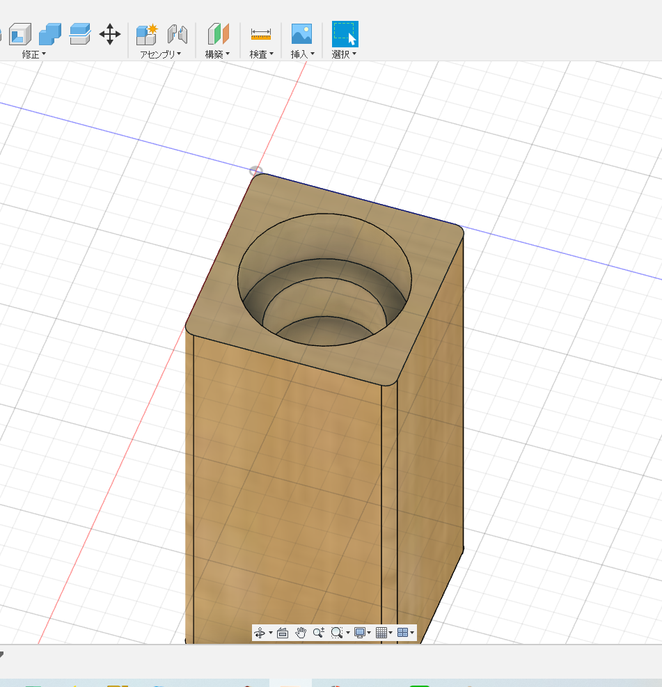
You can secure wood by buying wood with a thickness of 45 mm x 45 mm at a home center and cutting it out at 100 mm intervals.
Using a 35mm hole saw, make a hole for mounting the board from the back. Make a hole to insert the test tube with a 25 mm hole saw from the top.
The 2D drawing is shown below.
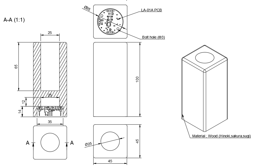
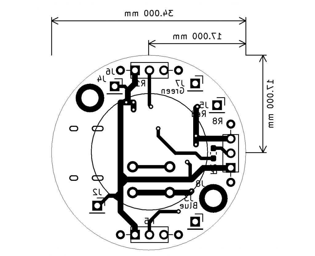
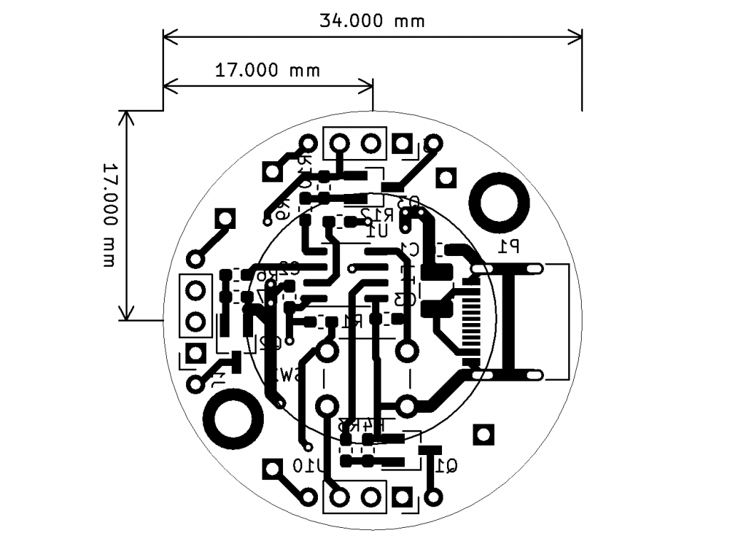
Therefore, I decided that the size to put the board in is 35mm in diameter, so I think that the size of the board should be 34mm in diameter.
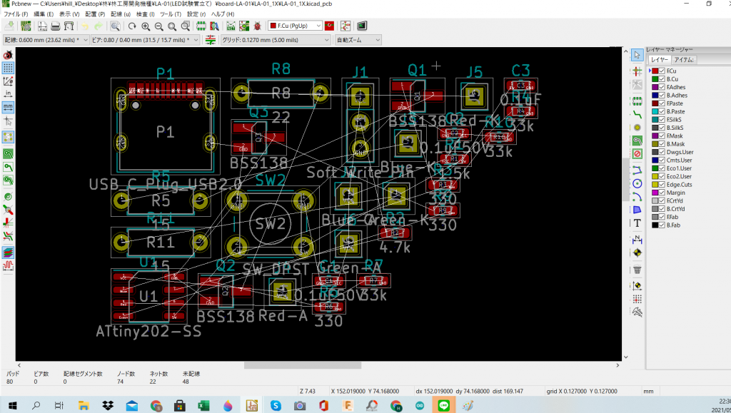
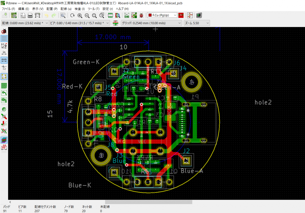
Let’s get started to design the PCB.
Board is 2 Layer.
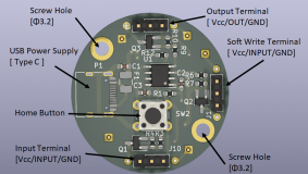
The contents of the board are shown in the figure below. Power is supplied from USB-type C.
In addition, power supply, color switching, brightness adjustment, etc. are all integrated into one home button.
After that, I would like to link the terminals for writing software and the same boards when expanding within the same product in the future. For that purpose, we have prepared a signal input terminal and an output terminal. After that, there are two screw holes Φ3.2 for fixing the board.
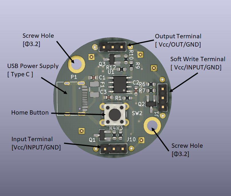
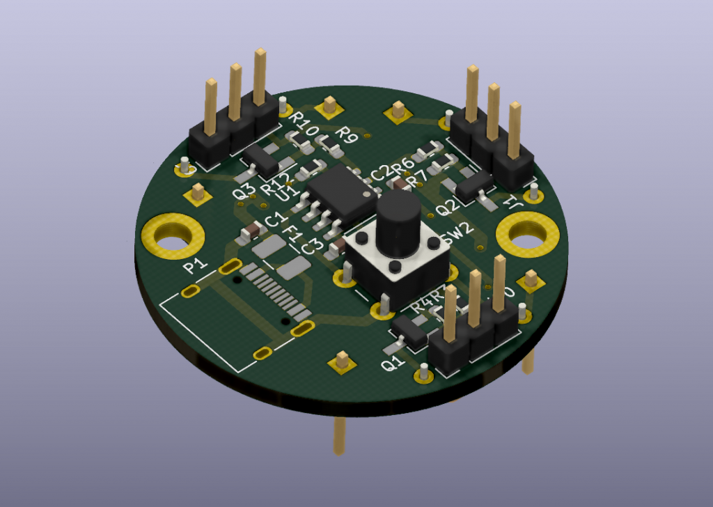
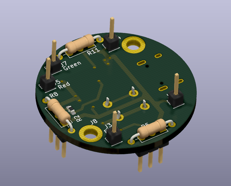
The front and back sides are shown in the figure below. There is a space in the middle of the TOP where you can place the full color LED.
The 2D drawing is shown below.
After making the drawing, we will check the actual product.
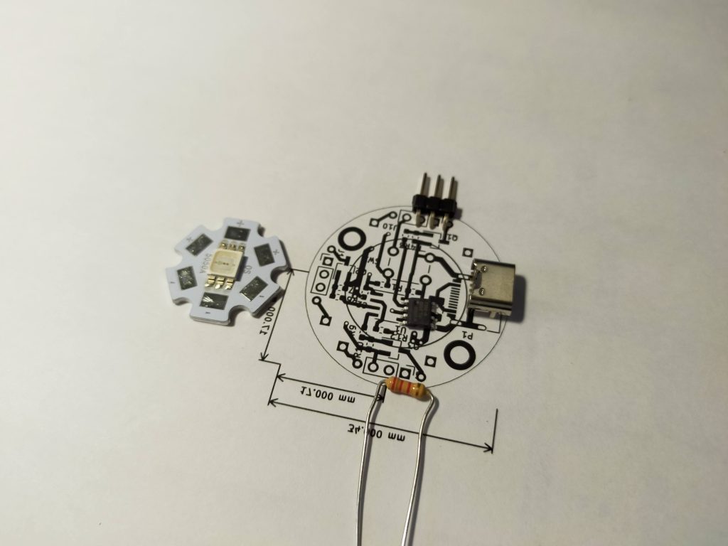
Print the drawing to full size and actually place the part on top to see if it is the correct size.
This completes the design. Next time, I will order the board from a vendor.