Sep.3.2021 AM / FM radio reception principle

・Features of AM and FM

I think that radio waves come to mind when you think of radio waves. However, the radio waves themselves cannot transmit audio or video.

It is necessary to devise some kind of radio wave.

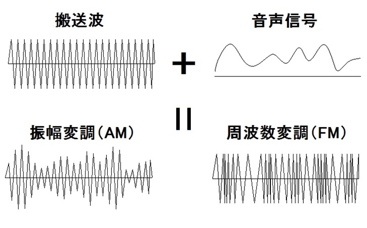
Here, the radio wave is put on the radio wave using a technique called modulation that synthesizes the audio signal and the radio wave. Modulation includes Amplitude Modulation for AM radio broadcasting and Frequency Modulation for FM broadcasting.

Amplitude modulation is a method that changes the amplitude of a carrier wave (high frequency) up and down. This method is technically simple and has been used for a long time, but due to its nature, it is easily affected by noise and the sound quality is not very good.

On the other hand, frequency modulation is a method of partially changing the frequency of the carrier wave, and synthesizes with dense waveforms. When the amplitude of the audio signal is low, the waveform of the transmitted wave becomes sparse, and when it is high, the waveform becomes dense.

AM radio reception principle (envelope detection)

The reception principle of AM radio is very simple. Since the amplitude of the received radio wave is the audio signal as it is, it is OK if the carrier wave component is removed.

The simplest representation of

AM radio is shown below.
This is often referred to as germanium radio.


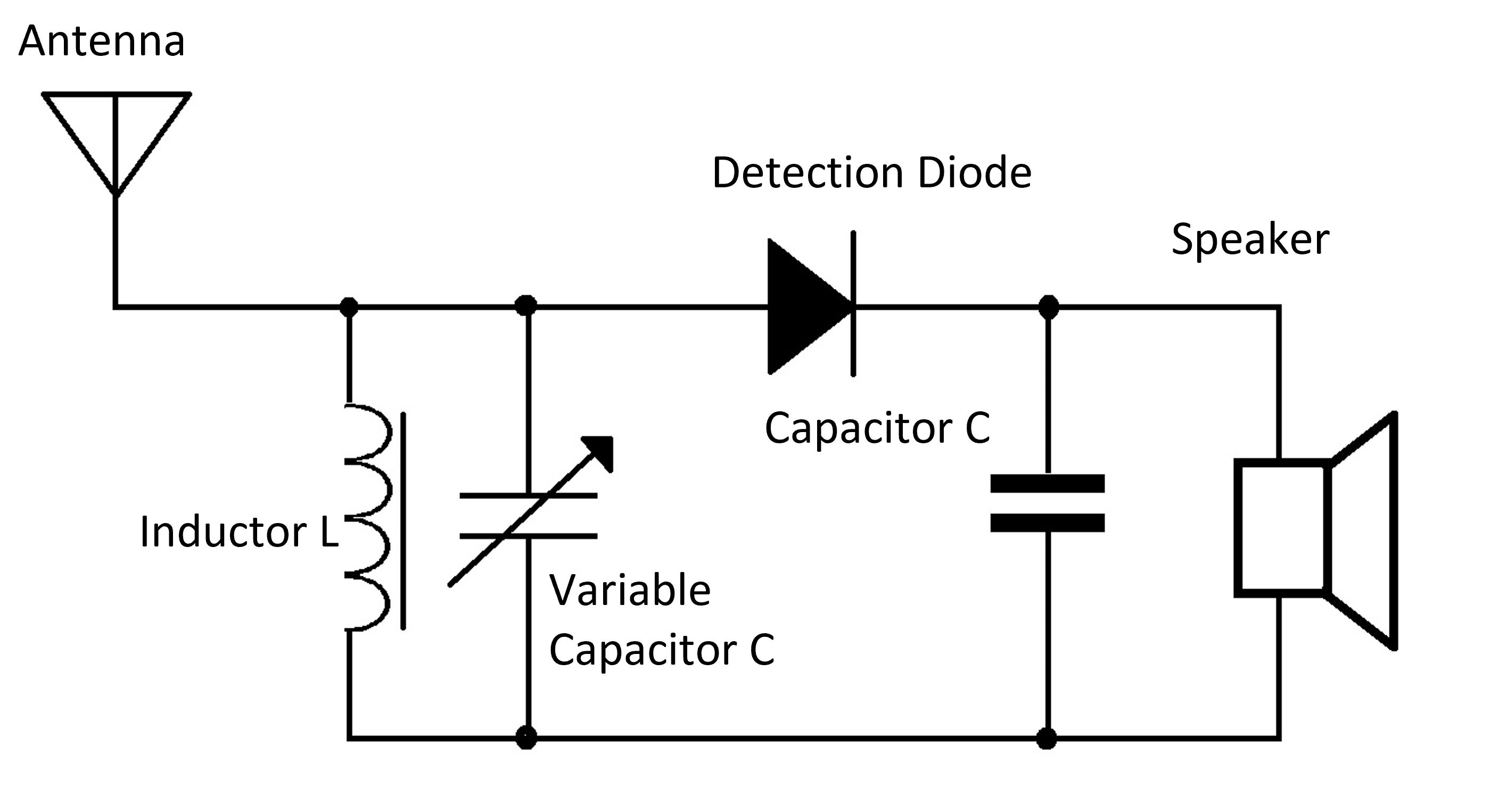
The antenna receives radio waves from many broadcasting stations.
Therefore, it is necessary to select the desired broadcasting station from them. Therefore, prepare a resonance circuit that connects a coil and a variable capacitor (variable capacitor) in parallel, and cut radio waves other than the desired frequency.
Next is the detection circuit. It uses diodes and capacitors to remove carrier components.
As a result of removing, only the audio component remains.
Since this detection diode uses a germanium diode, it is often called a germanium radio.


AM radio reception principle (Straight radio)

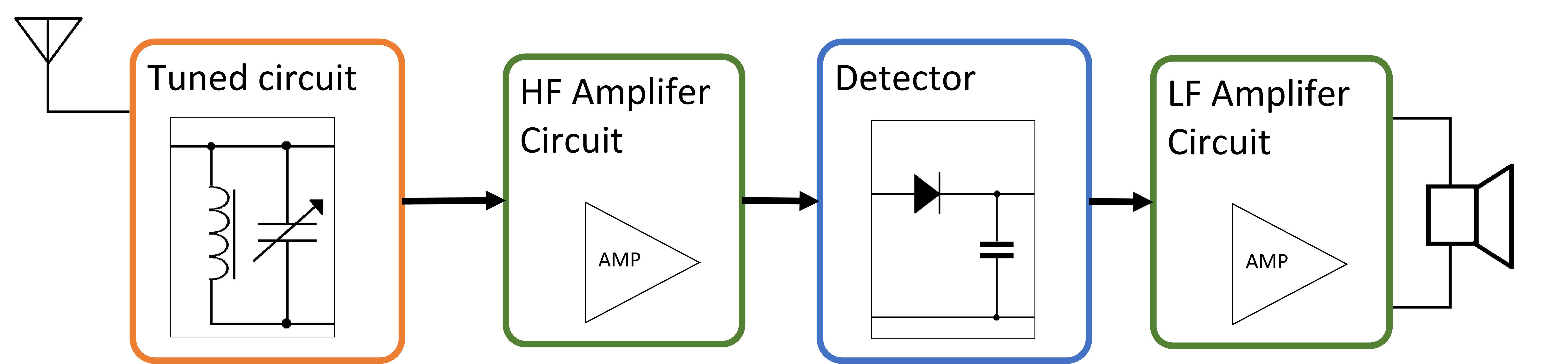
The germanium radio I introduced earlier is too low in sensitivity and volume.

Therefore, in a general AM radio, the tuning circuit and the detection circuit have almost the same shape, but an amplifier circuit is inserted in each. First, a high-frequency amplifier circuit is inserted in the output of the tuning circuit to increase the sensitivity. Then, in order to hear at a louder volume, an amplifier circuit is inserted in the output of the detection circuit so that it can be heard through speakers.


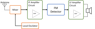
FM radio reception (superheterodyne)

The most common FM radio is the superheterodyne system.
I would like to explain this in detail next time, but I will briefly explain it below.
The best feature of the superheterodyne receiver is that the received signal is lowered to a lower frequency band before detection and demodulation. Lowering the frequency has the advantage of increasing sensitivity and frequency selectivity.
To lower the frequency, mix the signal received by the antenna with the high-frequency signal prepared by the local oscillator circuit using the mixer, as shown in the figure below.
Then, the frequency of the difference (beat) between the mixed wave and the received wave is generated.
By extracting this beat and detecting it (changing FM radio waves into voice), a stable and high-quality radio can be produced.

That’s all for today.

Aug.27.2021 I tried disassembling KTF5002

We are planning a new project from this time.
Disassemble a commercial product and learn the technology hidden in it.
This time, I will disassemble the AM / FM radio tuner, KTF5002 made by KENWOOD.
This was sold at HARDOFF in the neighborhood for 1500 yen.

It was a junk item, but it was in good condition, and both FM and AM radios sounded fine.

Can Receive FM radio

Can Receive AM radio

First of all, I investigated this radio.

When I looked it up, it was released around 1997. It’s one below from my age.
The price is reasonable at 25,000 yen.

The pdf of the instruction manual was also included, so I will paste the link below.

KTF-5002data sheets

This is a Specfication bellow.


Reception frequency range of FM radio is 76MHz to 90MHz. It is enough range for FM radio at that time.

Over 90MHz was the band of analog TV audio signals. Currently, this vacant band is the complementary broadcast of AM radio (WideFM).Total harmonic distortion is 0.5%, which is reasonable for audio equipment.

What surprised me personally was that the SN ratio of the FM radio was 70 dB. I think the performance is quite high for that time.

In addition, the SN ratio of AM is 40 dB. After all, AM radio has more noise than FM.


Front panel

It seems that you can set Auto (automatic tuning), sleep, time reservation, etc.

At first glance, I thought it was a volume, but this is a channel selection. You can’t spin it around, just tilt it.

The back is like this. There are FM antenna terminal, AM antenna terminal, audio output, outlet, and detection output. The FM antenna terminal is the same as the TV antenna wire.

Let’s remove the cover and take a look at the contents.

I see. I thought it was complicated, but the contents were contained in one board.
Take out the board further.
Roughly, the name of the circuit is shown.
It consists of many circuits such as FM front end, FM multiplexer, AM stereo demodulation circuit, PLL circuit, power supply circuit, etc. I will explain these circuits one by one in future blogs.

Today, I just disassembled it, so I will focus on the entire board.

First, the material of the substrate is a paper phenol substrate. It’s cheap and not very durable, but it’s good enough for stationary audio equipment. The board has a one-sided single-layer structure, and the parts are attached to only one side. Therefore, jumper lines are often used because of the intersection of lines. In addition, the surface mount components are only the microcomputer (thick, …) attached to the back surface, and all the rest are discrete components. All of this part is manually inserted, where the legs of the part are bent behind the board. And you can see that it is cut by human hands.

Also, since there is no unevenness in the soldering, it can be seen that the board is applied to the solder bath and the soldering is done by the flow method. Only the microcomputer may be retrofitted and reflowed with cream solder.

Honestly, I think that this is a considerable labor cost from the current era.

I think it’s amazing that this is sold for 25,000 yen.

Also, the power supply circuit is also noteworthy.

Audio-related equipment is so heavy because it does not use a switching method in the power supply circuit. Switching power supplies are, for example, mobile phone chargers and personal computer charging adapters. If you use switching, the circuit of this radio will be lighter, but switching will generate a lot of noise, so if you use it as a power supply for the radio, the SN ratio will drop at once. Therefore, there is no choice but to place a large transformer and make it with an old-fashioned power supply circuit.

In addition, the display is a display method called VFD. Often, at the supermarket cashier, the pale letters “Gokei 2350 En” appear. Nowadays, there are many liquid crystal displays (calculators, etc.) and LEDs, but this is an old-fashioned display that applies vacuum tube technology.

I hope I can write this in detail in future blogs.

Finally, the back side of the switches. It was pretty simple.

Today was a roughly disassembled report. In the future, I would like to analyze this product in more detail with the following plan. Next time, I will explain the reception principle of AM radio and FM radio on 9/2. I will also touch on the story of PLL and MPX.

Current serialization; “Disassembly survey of FM / AM stereo tuner KTF-5002”

Update      Content          
8/26I disassembled KTF5002 (specifications, disassembly procedure, board configuration, mechanism)
9/2AM / FM radio reception principle (AM / FM is the main reception method used, what is PLL / MPX)
9/9I investigated the IC used in KTF5002
9/16About FM front-end circuit, FM-IF circuit, AM-RF circuit
9/23PLL circuit principle
9/30About FM-AM DET circuit
10/7About FM-MPX circuit
10/14About Audio AMP circuit
10/21About power supply circuit
10/28About VFD display circuit

Aug.20.2021 Disassembled the mysterious box

The day before yesterday, I went to Hard Off in my neighborhood and bought an unfamiliar box and a wii remote controller on impulse for disassembly.


This time, I will confirm the identity of this mysterious wooden box.

Even if I don’t know what’s inside, I thought this case could be used in many ways.

First of all, there are 6 spaces on the top where you can put something.

And there were three buttons next to it.


The place to put something was two magnets and three terminals in the middle.

Two hypotheses are possible, one is that these two magnets are + and-of the power supply, respectively, and the middle three may be signal lines (three are SPI communication). I have.

Another hypothesis is that no voltage is applied to the magnet, two of the three terminals are + and-of the power supply, and the other one is the signal line. If there is not a lot of data (7 segments, etc.), I think that there is no problem with control like a servo motor.

The back side only has a DC jack.

The voltage is not written and I am scared so I have not applied the voltage yet. The DC jack is a 2.1φ one sold in Akizuki, so it feels very close to you.

Let’s open the inside now.

! !! !! !! !! !! !! !! !!

It was very simple inside. First, there is a microcomputer, a crystal, and a coin battery in the middle.

Let’s take a closer look at the board.

First, from the board, this is a clock.

The microcomputer chip that controls the display system uses ATmega8A, and a 16MHz general crystal oscillator is used for the clock. Also, I think the chip next to it is the RTC (real-time clock).

This is an element that keeps ticking the time accurately and keeps sending the data of the current time to the microcomputer. Even if the power is removed, coin batteries are loaded so that the time can be kept ticking with the least power consumption. The voltage of the coin battery is 3V, while the voltage supplied from the power supply is 5V, so the voltage of the power supply does not flow into the coin battery and the voltage of the coin battery does not flow into the microcomputer etc. There are two.

There were also unmounted parts. First, the 6-pin terminal next to the microcomputer is the program writing terminal. You can easily rewrite the program by connecting it to the ISP terminal of Arduino.

Also, I am concerned about unmounted parts. Especially, the unmounted terminal written as JDY-16 is worrisome. This is a Bluetooth communication module. Perhaps it is for connecting to a smartphone etc. and making the watch such a thing or something like this. I wonder if there are some options. I do not know.

I checked it because it was written on the board as GIXIE CLOCK.

It seems that I got something more amazing than I expected.

After all it was a clock.

Paste the link below.

AZUREST✖️Gixie Clock

These cases seem to be very useful, so I’ll think about something.

It was very interesting.