2021.9.4 Circuit design for GIXIE Audio

We will design the circuit of the circuit block designed in the block diagram last time.
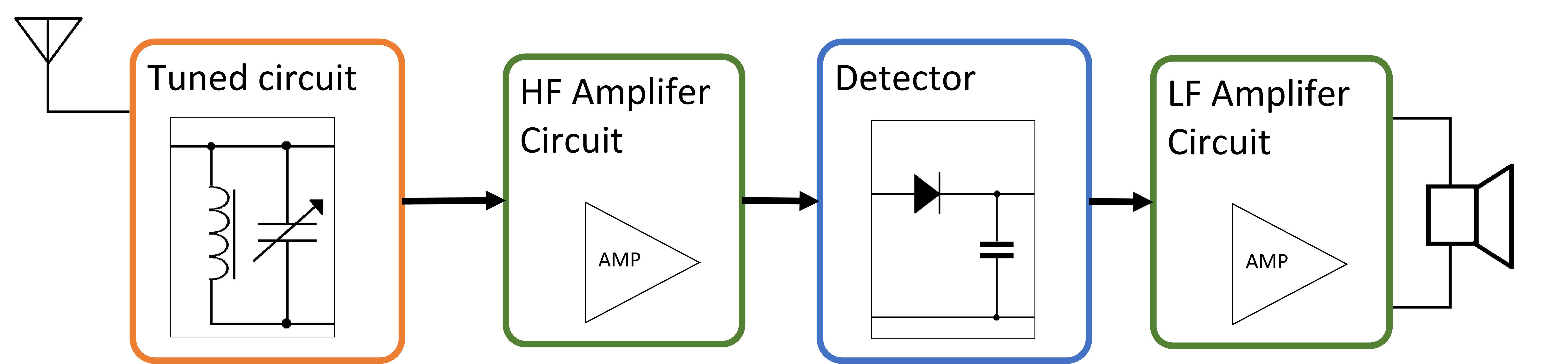
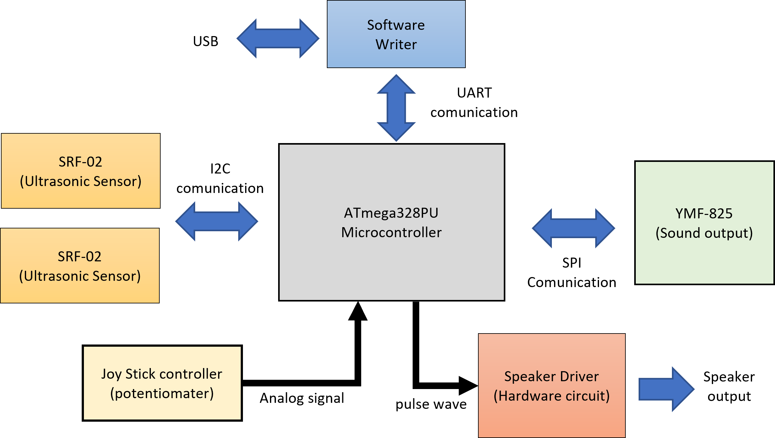
The block diagram shown last time is shown below.

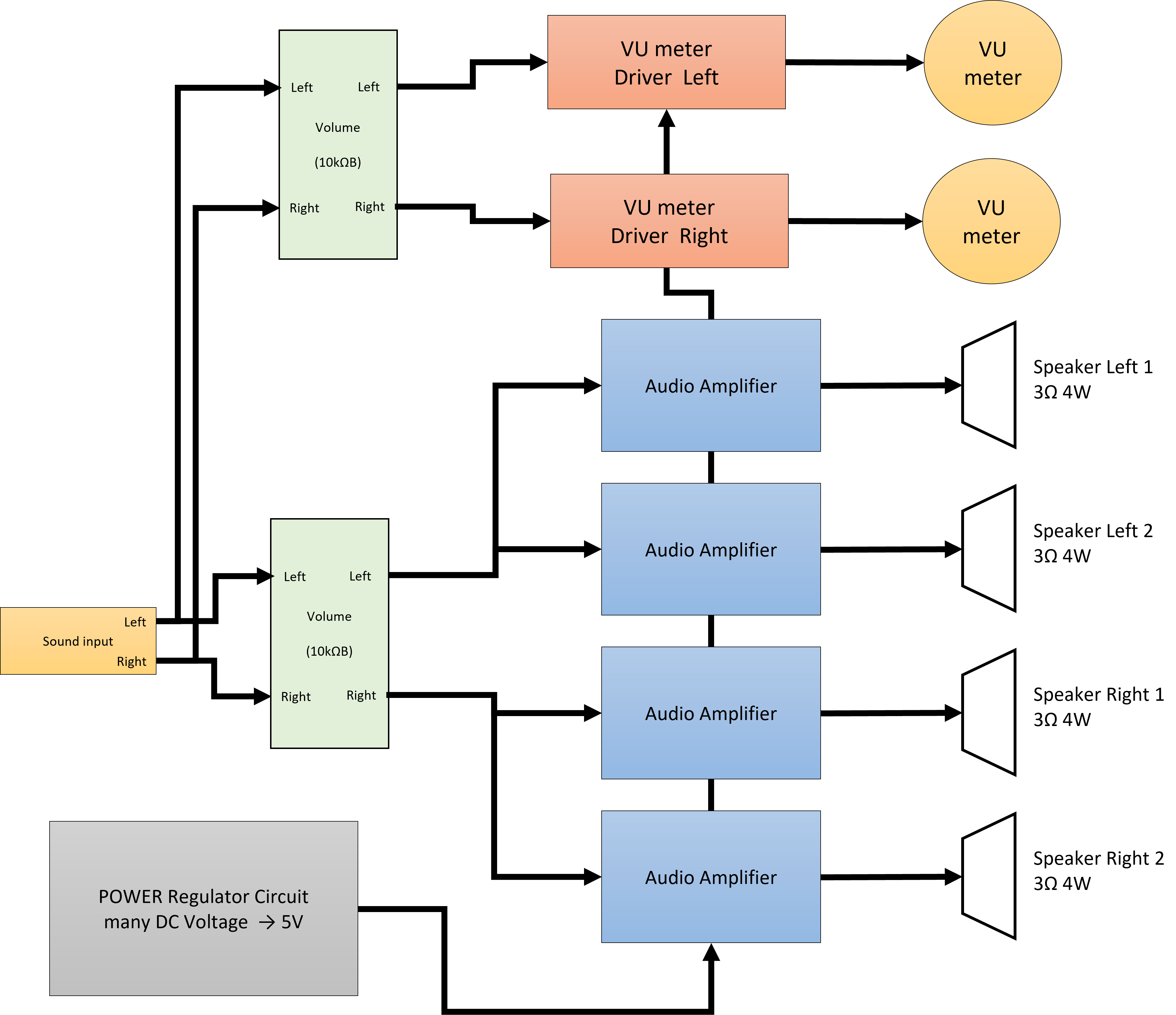
There are three circuit blocks that have design elements here. Audio Amplifier, Power Regulator, and VU meter driver.
First, the circuit diagram of the designed amplifier is shown below.

Audio Amplifer

This is an amplifier Circuit below.

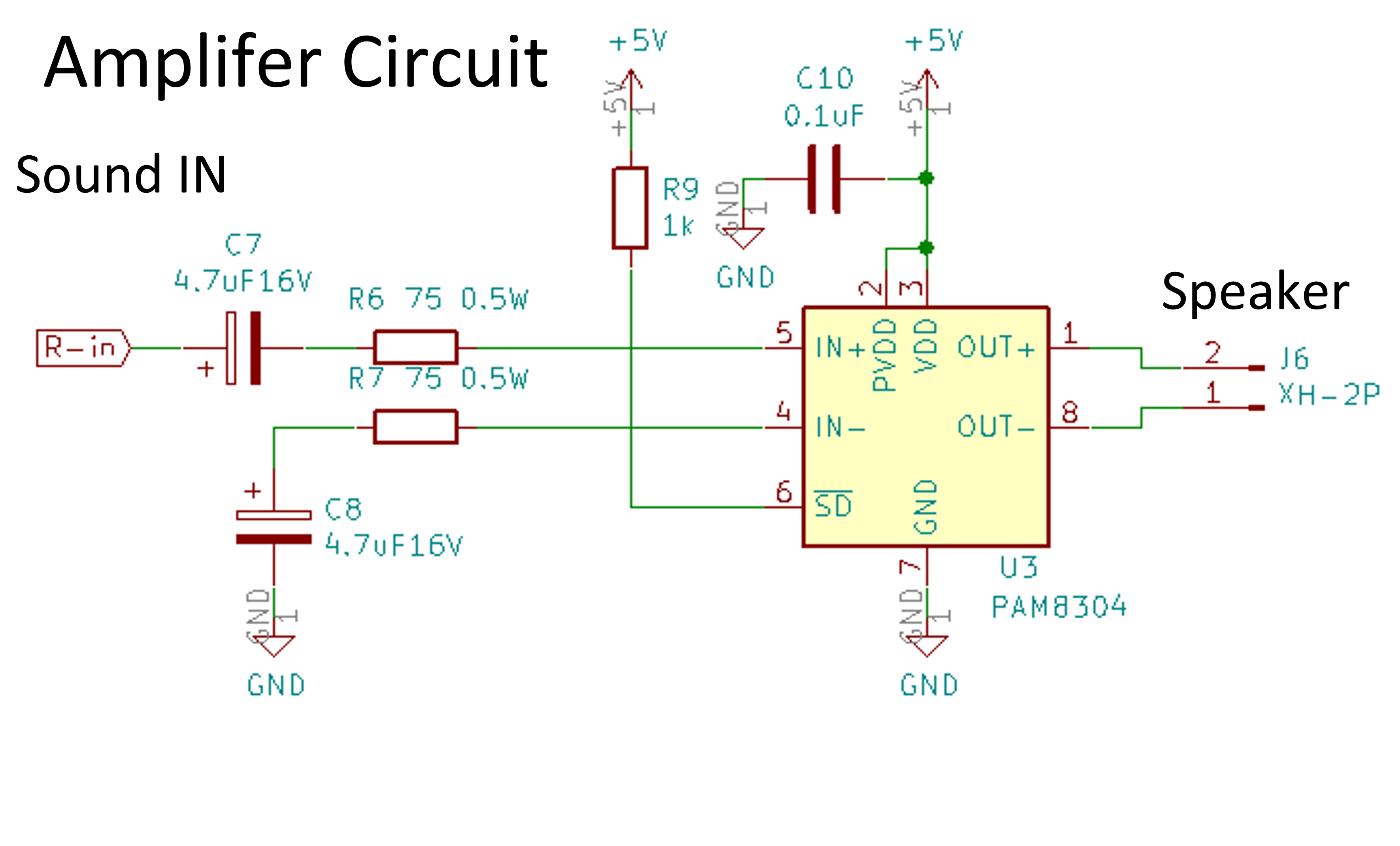
I used an amplifier IC (PAM8304) that does not require detailed design.

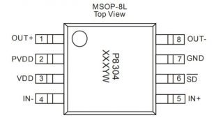
D Class Amplifer IC PAM8304ASR

■Summary
・Power Voltage:2.8~6V
・Output:
3W typ(5V・4Ω)
1.75W typ(5V・8Ω)
・Gain:300000/Rin
(30倍 about Rin 10kΩ)
・Loss Current at No signal:5mA typ(VDD=5V)
・Power efficiency:93% typ(RL=8Ω、THD=10%)
・Package:0.65mm、MSOP8

**Quoted from HP of Akitsuki denshi**

For the circuit, I used the reference circuit described in the data sheet here. The resistance value and the capacitor were decided sensuously.

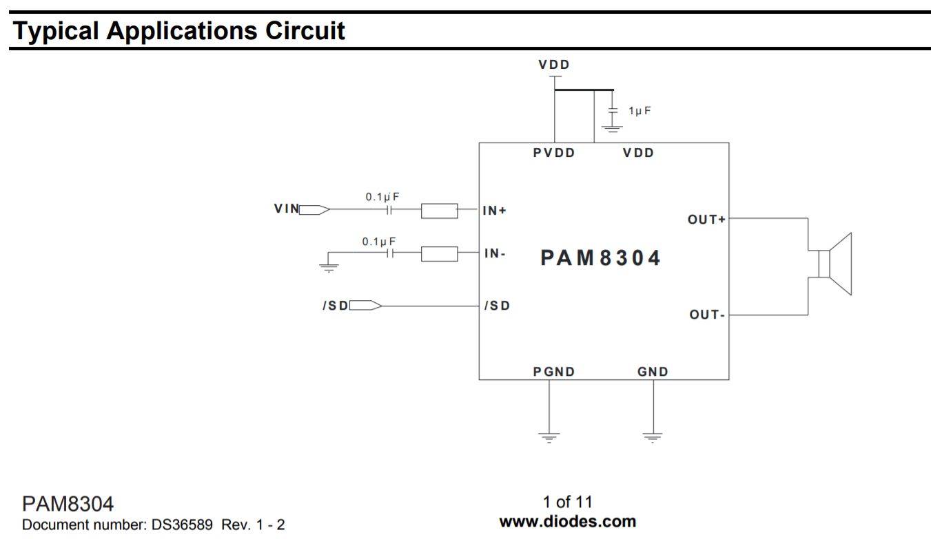
The SD (shutdown) terminal is pulled up because it will stop unless it is pulled up.


VU meter circuit

Next is the circuit of the VU meter.

The VU meter is, so to speak, a DC ammeter. Instead of inputting the audio signal directly, it is amplified by an operational amplifier, rectified by a diode (converted from AC to DC), and the current is adjusted by a resistor and sent to the VU meter.

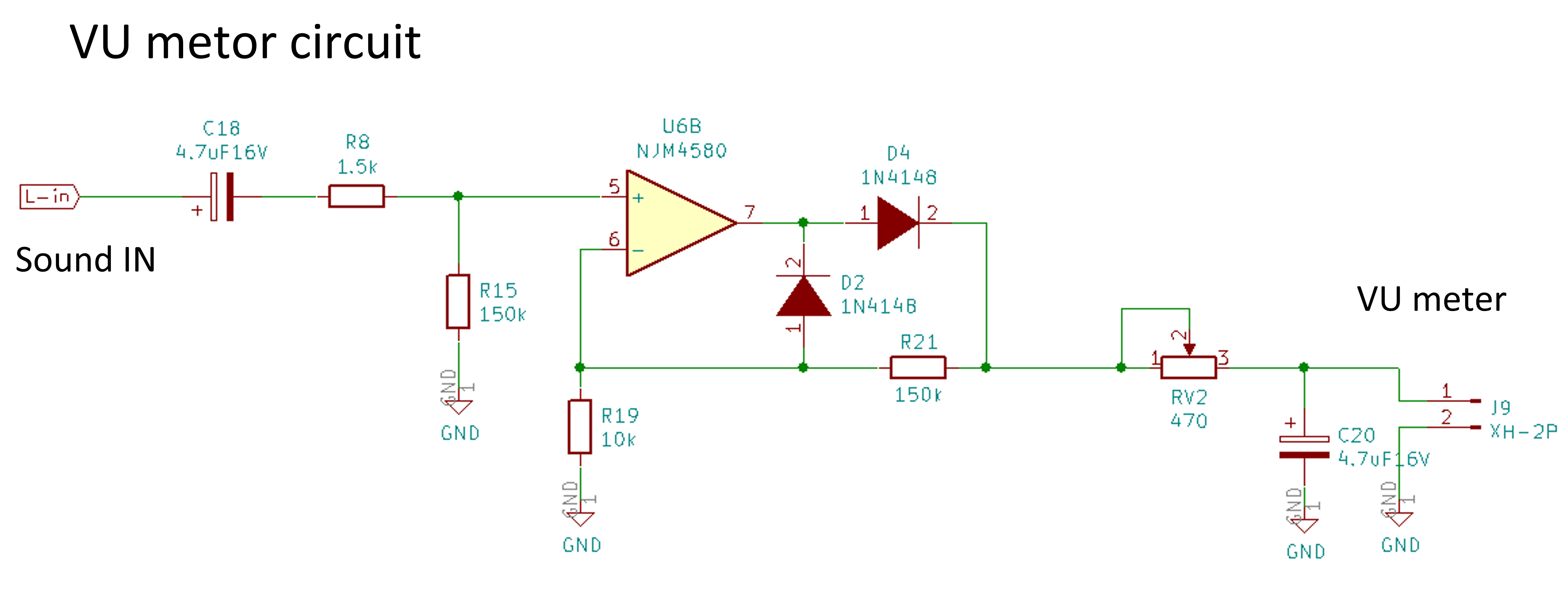
For the OPAMP, I used NJM4580, which can be used for general purposes.


Power Regulator Circuit

Next is the power supply circuit.
Since the power supply voltage of the amplifier ICPAM8304 is 6V at maximum, a circuit that can flow a constant voltage of 5V is required.

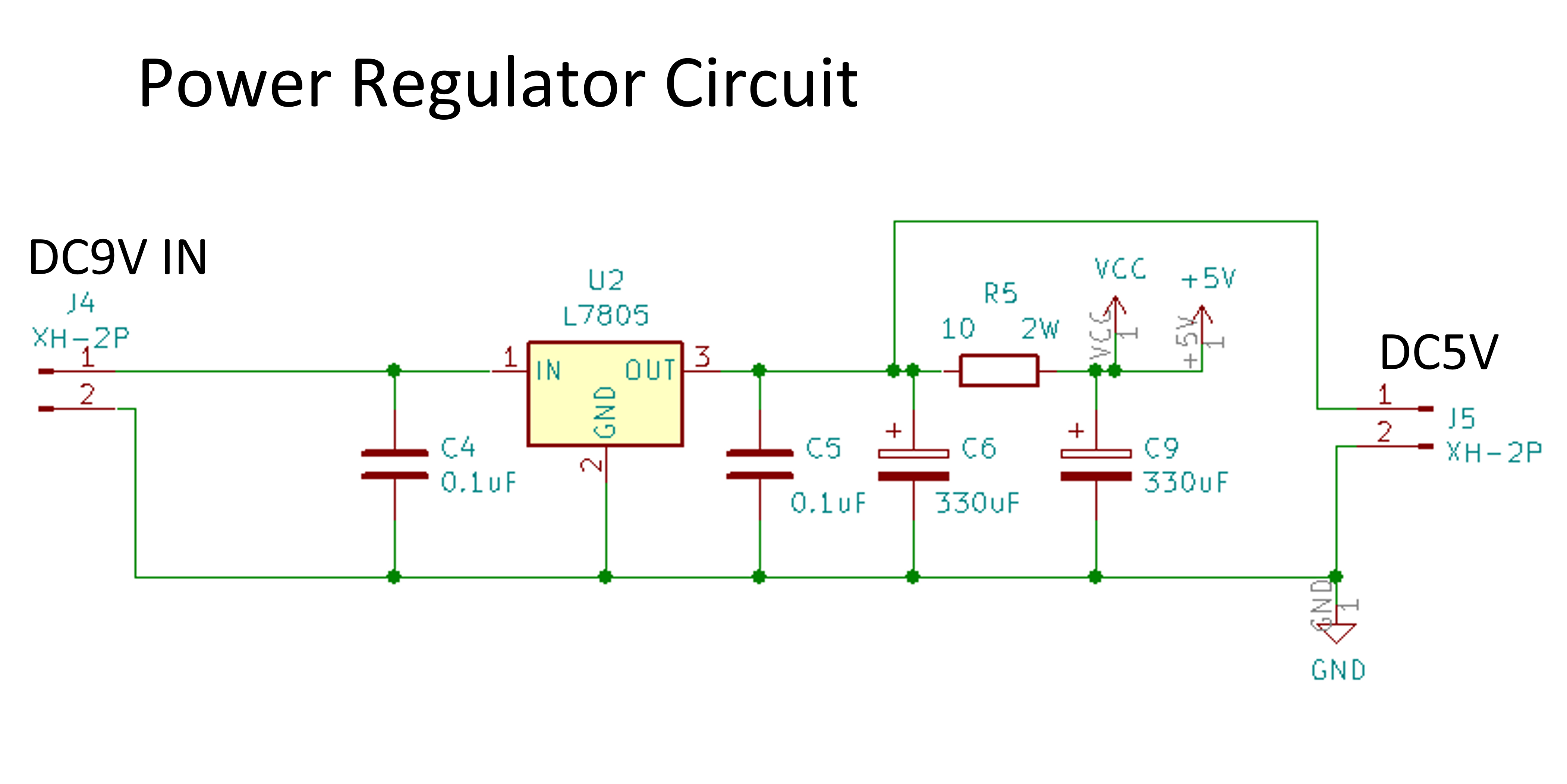
The circuit is a general circuit of a 3-terminal regulator. C4 and C5 are anti-oscillation capacitors. C6 is for ripple removal. It is also an RC low-pass filter for R5 and C9.


Regulator IC  5V1.5A TO-252 NJM7805SDL1

■ Main specifications
-Output method: Series
-Output positive / negative: Positive power supply
-Input voltage: ~ 35V
-Output voltage: 5V
-Maximum output current: 1.5 A
-Dropout voltage: 2.2V
-Allowable loss: 1190mW
-Ripple removal ratio (PSRR): 78dB
-Package: TO-252

** Quoted from Akizuki Denshi **

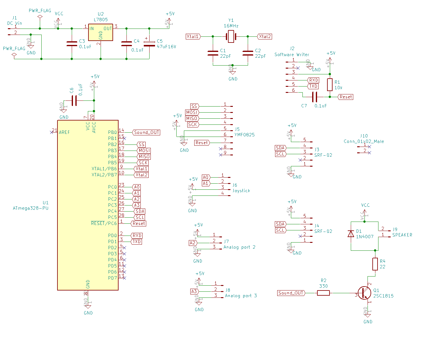
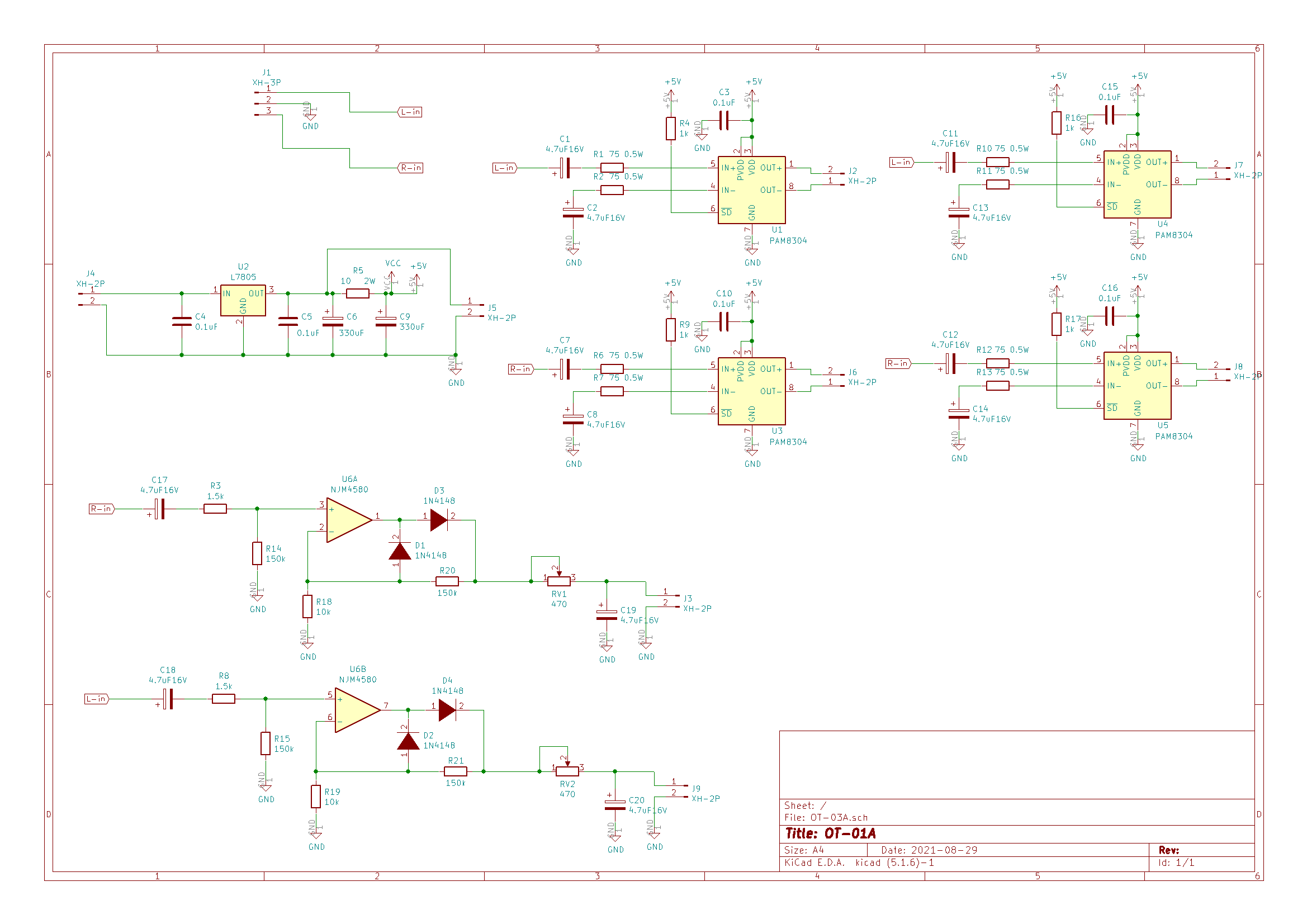
Finally, the entire schematic is shown.

Next time, we will design the board for this circuit.

Sep.3.2021 AM / FM radio reception principle

・Features of AM and FM

I think that radio waves come to mind when you think of radio waves. However, the radio waves themselves cannot transmit audio or video.

It is necessary to devise some kind of radio wave.

Here, the radio wave is put on the radio wave using a technique called modulation that synthesizes the audio signal and the radio wave. Modulation includes Amplitude Modulation for AM radio broadcasting and Frequency Modulation for FM broadcasting.

Amplitude modulation is a method that changes the amplitude of a carrier wave (high frequency) up and down. This method is technically simple and has been used for a long time, but due to its nature, it is easily affected by noise and the sound quality is not very good.

On the other hand, frequency modulation is a method of partially changing the frequency of the carrier wave, and synthesizes with dense waveforms. When the amplitude of the audio signal is low, the waveform of the transmitted wave becomes sparse, and when it is high, the waveform becomes dense.

AM radio reception principle (envelope detection)

The reception principle of AM radio is very simple. Since the amplitude of the received radio wave is the audio signal as it is, it is OK if the carrier wave component is removed.

The simplest representation of

AM radio is shown below.
This is often referred to as germanium radio.


The antenna receives radio waves from many broadcasting stations.
Therefore, it is necessary to select the desired broadcasting station from them. Therefore, prepare a resonance circuit that connects a coil and a variable capacitor (variable capacitor) in parallel, and cut radio waves other than the desired frequency.
Next is the detection circuit. It uses diodes and capacitors to remove carrier components.
As a result of removing, only the audio component remains.
Since this detection diode uses a germanium diode, it is often called a germanium radio.


AM radio reception principle (Straight radio)

The germanium radio I introduced earlier is too low in sensitivity and volume.

Therefore, in a general AM radio, the tuning circuit and the detection circuit have almost the same shape, but an amplifier circuit is inserted in each. First, a high-frequency amplifier circuit is inserted in the output of the tuning circuit to increase the sensitivity. Then, in order to hear at a louder volume, an amplifier circuit is inserted in the output of the detection circuit so that it can be heard through speakers.


FM radio reception (superheterodyne)

The most common FM radio is the superheterodyne system.
I would like to explain this in detail next time, but I will briefly explain it below.
The best feature of the superheterodyne receiver is that the received signal is lowered to a lower frequency band before detection and demodulation. Lowering the frequency has the advantage of increasing sensitivity and frequency selectivity.
To lower the frequency, mix the signal received by the antenna with the high-frequency signal prepared by the local oscillator circuit using the mixer, as shown in the figure below.
Then, the frequency of the difference (beat) between the mixed wave and the received wave is generated.
By extracting this beat and detecting it (changing FM radio waves into voice), a stable and high-quality radio can be produced.

That’s all for today.

sep.1.2021 Circuit design of OT-01

In the previous blog, I even designed a block diagram of an ultrasonic musical instrument.
I will start circuit design at once.
The following is the block diagram designed last time.

In short, how to connect each module to the microcomputer is important.
First, check the pin layout of the microcomputer to be used.

pin asign ATmega328PU
Communication port of ATmega328PU

Connected to SRF-02

SRF-02 communicates in the format of I2C.

I2C connection method is very easy. This time, we will make it possible to connect two ultrasonic sensors in parallel.

For I2C communication, connect the four terminals of Vcc and GND power supply terminals, synchronous clock SCL, and signal line SDA of the sensor (Slave) and microcomputer (Master), respectively.

Even if they are connected in parallel, there is no problem because the addresses are assigned to each sensor.

Connected to YMF-825

YMF-825 communicates by SPI.

SPI communication is from Vcc and GND power terminals on the sound source IC (Slave) and microcomputer (Master), SS (Slave Select) that selects the SCK of the synchronization clock and the Slave to be connected, and from Master to Slave. There are MOSI (Master Out Slave In) that sends a signal and MISO (Master In Slave Out) that sends a signal from Slave to Master, and it consists of a total of 6 lines.

Software Writer

Software writing is I introduced it in the previous blog .

Since soft writing communicates via UART, connect the TXD (transmission) of the converter to the RXD (receive) of the ATmega328, and connect the RXD (receive) of the converter to the TXD (transmission) of the ATmega328. After that, the + 5V and GND of the TTL converter are also supplied to the ATmega328. Then, connect the RTS and the ATmega328 Reset via a 0.1uF capacitor so that the converter can send a reset signal.

Speaker Driver

Depending on how you use YMF-825, you may run out of memory. For such a case, we have prepared a speaker driver circuit that can produce simple electronic sounds.

Previous blog It is also summarized in .

Finally, I wrote a circuit diagram that integrates these circuits.

Next time, I will design the board with KiCad.